
High-concentration waste water anaerobic fermentation device capable of realizing gas by-pass split-flow

A high-concentration wastewater and anaerobic fermentation technology, which is applied in the field of fermentation equipment and high-concentration wastewater anaerobic fermentation equipment, can solve the problem of poor treatment effect of anaerobic fermentation wastewater, decreased separation efficiency of three-phase separators, and influence on the concentration of anaerobic microorganisms, etc. problems, to achieve the effect of reducing the entrainment of sludge particles, improving the reaction effect, and maintaining the concentration of sludge particles

Inactive Publication Date: 2013-09-11
TIANJIN UNIV OF SCI & TECH +1
View PDF8 Cites 0 Cited by
  • Summary
  • Abstract
  • Description
  • Claims
  • Application Information

AI Technical Summary

Problems solved by technology

Since the methane gas will disturb and entrain the anaerobic sludge in the reactor during the rising process, when the high-concentration organic wastewater produces too much methane gas, the methane gas will form larger bubbles, and even form a rapidly rising The airflow, the sludge entrained by the rapidly rising air bubbles will reduce the separation efficiency of the three-phase separator on the upper part of the reactor, and it is difficult for the sludge particles to settle on the sludge bed, resulting in the loss of anaerobic microorganisms and affecting the internal exhaustion of the reactor. The concentration of oxygen microorganisms will eventually lead to poor treatment effect of anaerobic fermentation wastewater

Method used


Image

  • High-concentration waste water anaerobic fermentation device capable of realizing gas by-pass split-flow

Examples


Embodiment Construction

[0022] The present invention will be further described in detail below through the specific examples, the following examples are only descriptive, not restrictive, and cannot limit the protection scope of the present invention with this.

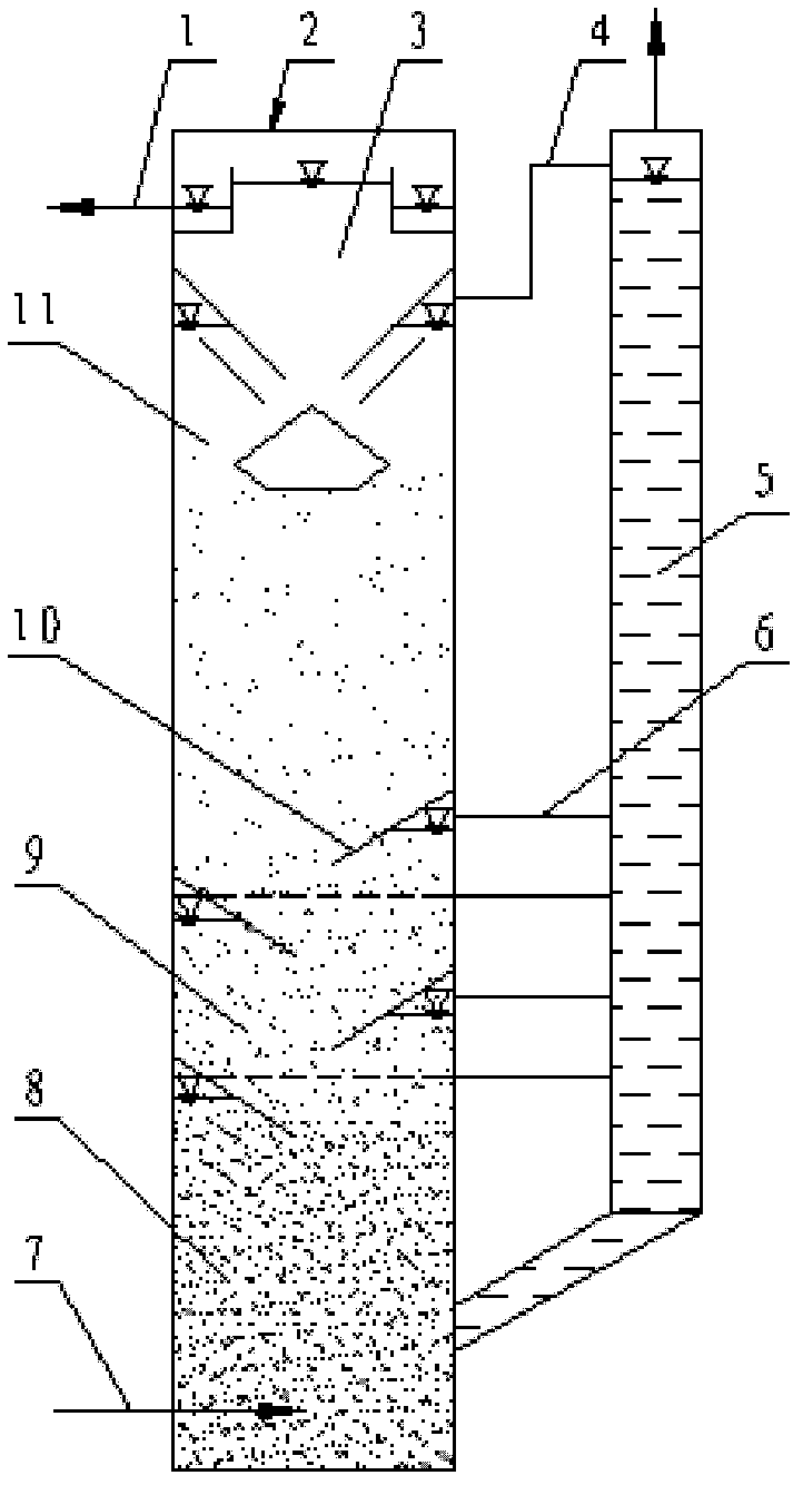
[0023] A high-concentration wastewater anaerobic fermentation device capable of realizing gas bypass diversion, including a reactor 11 mainly composed of a shell 2 and a three-phase separator 3, the three-phase separator is installed at the upper end of the shell, and the shell The lower part is provided with water inlet 7, the upper part of the shell is provided with water outlet 1, and the anaerobic sludge containing anaerobic microorganisms is placed in the reactor shell, and the anaerobic sludge forms a granular sludge layer 8 in the lower part of the shell. Form flocculent sludge layer 9 in the middle part.


PUM


Abstract

The invention relates to a high-concentration waste water anaerobic fermentation device capable of realizing gas by-pass split-flow. The high-concentration waste water anaerobic fermentation device comprises a reactor and a by-pass gas lifting pipe which is arranged at the outer part of the reactor and is communicated with the inner part of a shell of the reactor. The high-concentration waste water anaerobic fermentation device capable of realizing the gas by-pass split-flow, disclosed by the invention, is scientific in design, simple in structure, convenient in use and strong in practicability; since the bottom of the by-pass gas lifting pipe is communicated with the reactor, the lifting of the whole by-pass gas lifting pipe is balanced with that of the reactor, liquid does not flow and just plays a role in liquid sealing, the gas, at the position of an oblique inserting plate, can naturally enter into the by-pass gas lifting pipe, thus the large amount of gas accumulation at the inner part of the reactor can be greatly reduced, the granular layer can be stabilized, the aerogenesis can be facilitated, the problem of carrying granule sludge due to the fast ascending after the granule sludge is accumulated by the gas is better solved, the load of a three-phase separator at the upper part is reduced, the fermentation efficiency is increased, and the large amount of loss of the sludge is avoided.

Description

technical field [0001] The invention relates to a fermentation device in the field of wastewater treatment, in particular to a high-concentration wastewater anaerobic fermentation device capable of realizing gas bypass flow. Background technique [0002] In the production process of many brewing and biopharmaceutical industries, a large amount of high-concentration organic wastewater will be produced, such as alcohol, wine, citric acid, monosodium glutamate, starch and sauce and vinegar industries. If these high-concentration organic wastewater is not used effectively, it will directly The use of conventional biochemical treatment methods to meet discharge standards requires a large amount of energy and operating costs. In order to solve the above problems, currently high-concentration wastewater is usually treated with resource-based treatment technology, that is, the fermentation reactor is used to treat wastewater with anaerobic fermentation to produce methane gas with hi...

Claims


Application Information

Patent Timeline
Patent Type & Authority Patents(China)
IPC IPC(8): C02F3/28
Inventor 王昶李桂菊顾萍
Owner TIANJIN UNIV OF SCI & TECH
Learn More