Method of laser welding for steel sheet and laser welding apparatus
A laser welding and steel plate technology, which is applied in laser welding equipment, welding/welding/cutting articles, welding equipment, etc., can solve problems such as scale powder residue and steel plate surface defects, so as to reduce poor shape, reduce welding cracks, and improve productivity effect
- Summary
- Abstract
- Description
- Claims
- Application Information
AI Technical Summary
Problems solved by technology
Method used
Image

Examples
no. 1 Embodiment approach
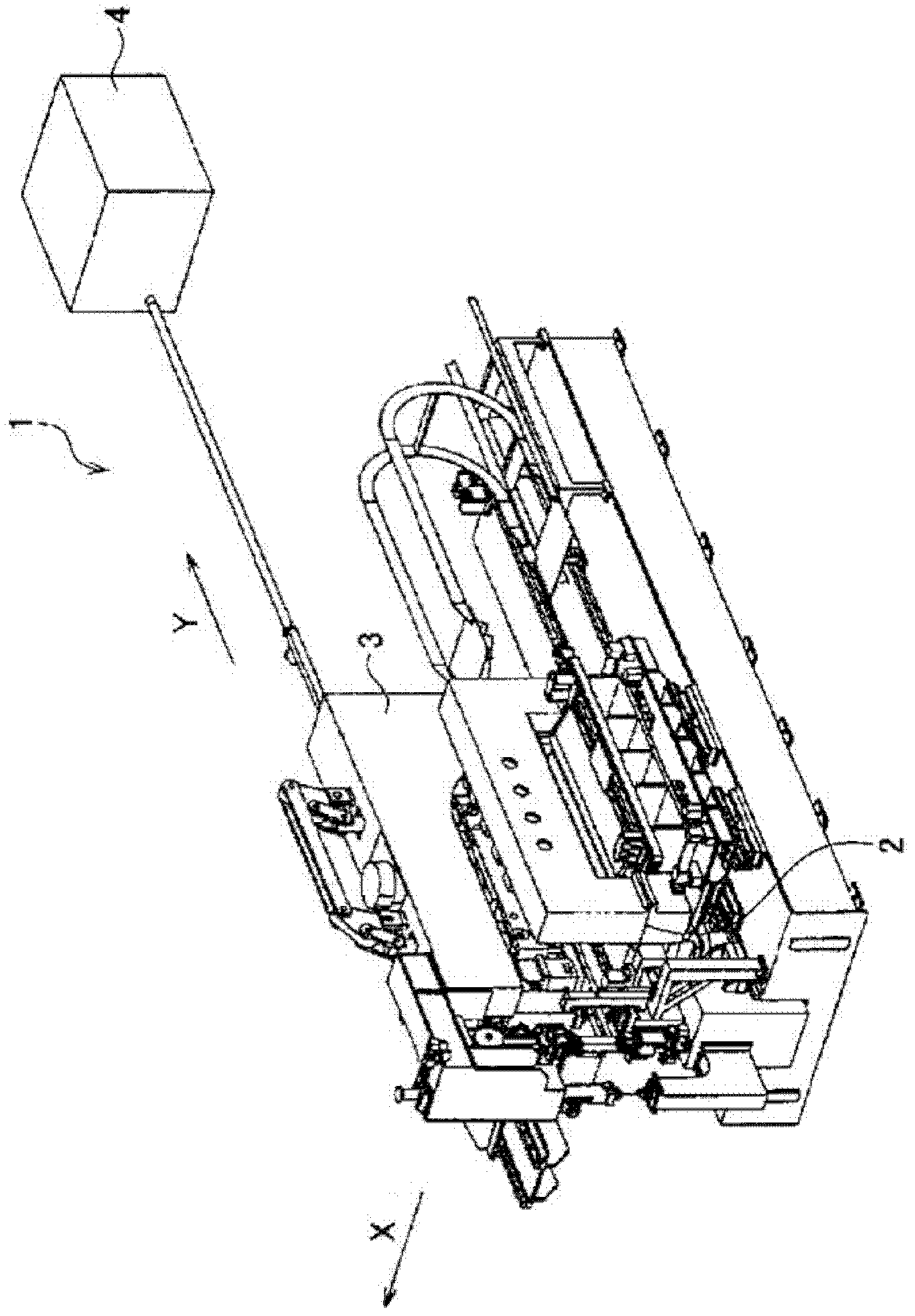
[0051] figure 1 It is a perspective view of the laser welding apparatus of 1st Embodiment of this invention.
[0052] Such as figure 1 As shown, the laser welding device 1 of the first embodiment includes: a jig 2 for holding a plate-shaped workpiece to be welded; figure 1 The welding carriage 3 that moves in the Y direction while welding the welded piece that is conveyed in the X direction; the carbon dioxide laser oscillator 4 .
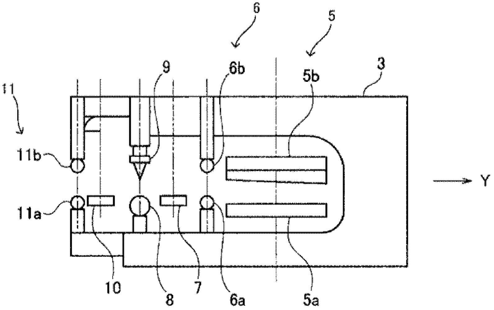
[0053] figure 2 It is a sectional view which shows the cross section of the welding carriage 3 of the laser welding apparatus 1 of 1st Embodiment.
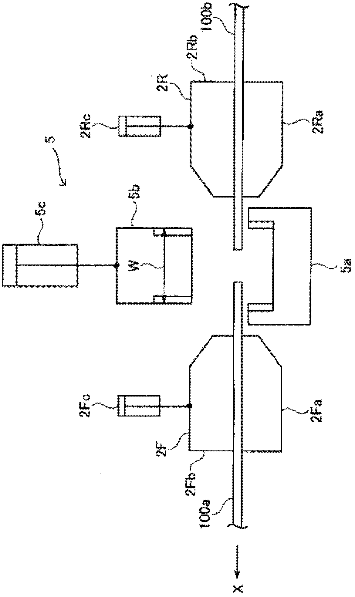
[0054] Such as figure 2 As shown, the welding carriage 3 includes: guillotine shears 5a, 5b, which are used as parts for cutting off the two ends of the transported workpiece to be welded; A part for shaping by pressing the butt part of the workpiece held by the jig 2; an induction heating head 7 for preheating, which is used as the first heater for inductively heating the workpiece after shapin...
no. 2 Embodiment approach
[0090] In the laser welding device 1 according to the first embodiment, a processing head 9 is provided for welding the workpieces 100a, 100b heated by the induction heating head 7 for preheating by irradiating laser light on the workpieces 100a, 100b to be welded.
[0091] In the laser welding apparatus 1a of the second embodiment, instead of the processing head 9, a processing head 9a having a function of injecting filler wire is provided.
[0092] The filler wire referred to here is a metallic welding material, and is often used especially when the workpieces 100a and 100b to be welded are difficult-to-weld materials such as high-carbon steel and high-Si steel. In the case of performing laser welding while injecting the filler wire into the welded portion by the processing head 9a, there is an effect of diluting the weld metal, and the welding quality can be improved. In addition, when the guillotine shearing machine 5 ages and the mechanical accuracy decreases, and the sha...
no. 3 Embodiment approach
[0099] Figure 12 It is a perspective view of the laser welding apparatus of 3rd Embodiment.
[0100] In the laser welding apparatus 1 according to the first embodiment, a carbon dioxide laser oscillator 4 and a machining head 9 for irradiating the laser beam transmitted through the air from the carbon dioxide laser oscillator 4 to the butted portions of the workpieces 100a and 100b to be welded are provided.
[0101] In the laser welding device 1b of the third embodiment, instead of the carbon dioxide laser oscillator 4, a YAG-based laser oscillator, or an oscillator 4b such as a fiber laser oscillator or a disk laser oscillator in which a plurality of fibrous crystals are arranged in parallel, is provided. A processing head 9b for irradiating the laser beam emitted from the oscillator 4b and guided by the optical fiber 12 to the butt portion of the workpieces 100a and 100b to be welded is provided.
[0102] In addition, the so-called fiber-shaped laser oscillator is a well-...
PUM
 Abstract
Description
Claims
Application Information
 - R&D
- Intellectual Property
- Life Sciences
- Materials
- Tech Scout
- Unparalleled Data Quality
- Higher Quality Content
- 60% Fewer Hallucinations
Browse by: Latest US Patents, China's latest patents, Technical Efficacy Thesaurus, Application Domain, Technology Topic, Popular Technical Reports.
© 2025 PatSnap. All rights reserved.Legal|Privacy policy|Modern Slavery Act Transparency Statement|Sitemap|About US| Contact US: help@patsnap.com