
Stationary constant-velocity universal joint

A constant velocity universal joint, fixed technology, used in elastic couplings, mechanical equipment, couplings, etc., can solve the problem of high impact force, achieve durability, suppress heat, and increase load capacity. Effect

Active Publication Date: 2014-11-26
NTN CORP
View PDF11 Cites 0 Cited by
  • Summary
  • Abstract
  • Description
  • Claims
  • Application Information

AI Technical Summary

Problems solved by technology

Therefore, as described above, when the vehicle collides, the propeller shaft is in a supported state, and the impact force generated by the vehicle becomes high.

Method used


Image

  • Stationary constant-velocity universal joint
  • Stationary constant-velocity universal joint
  • Stationary constant-velocity universal joint

Examples


Embodiment Construction

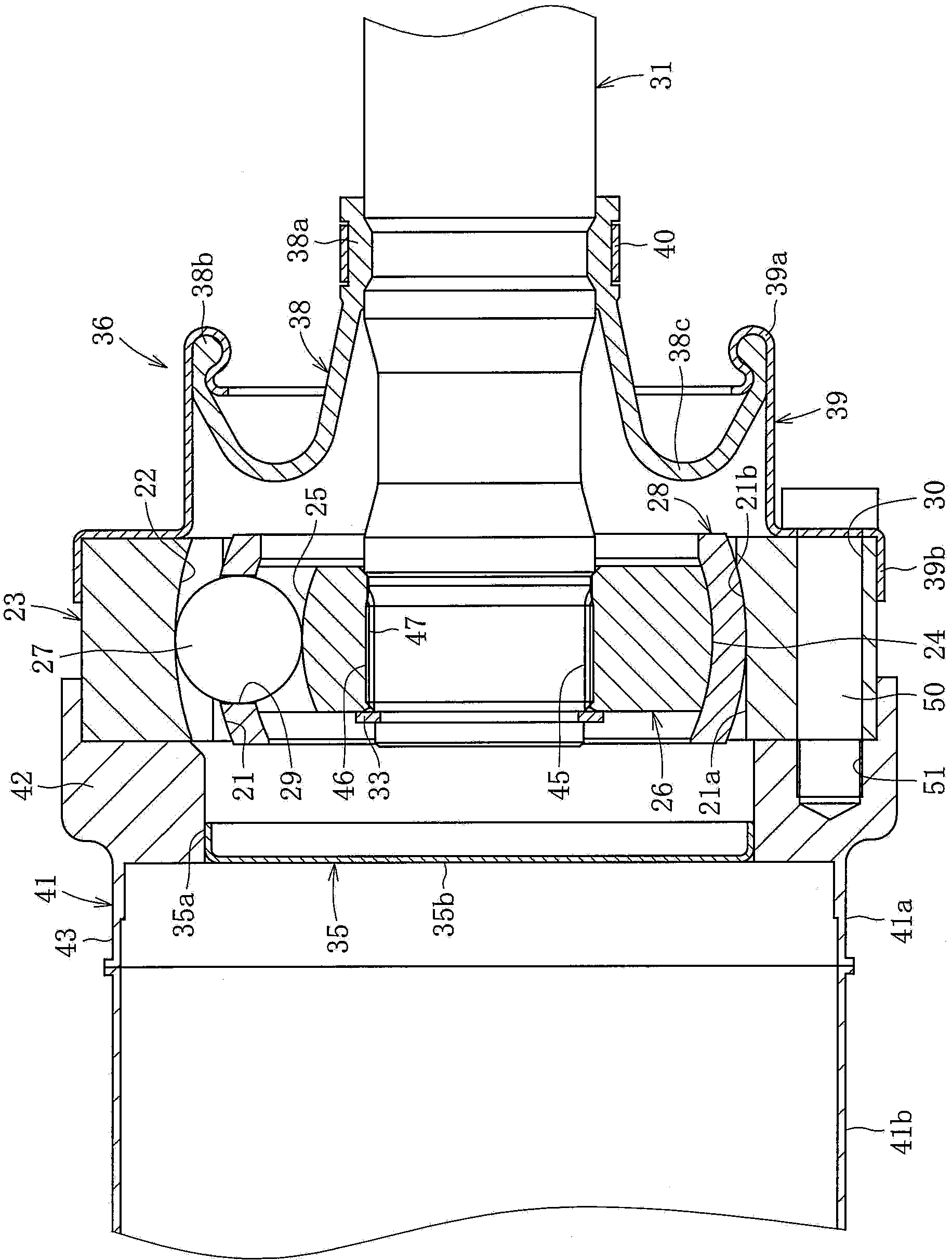
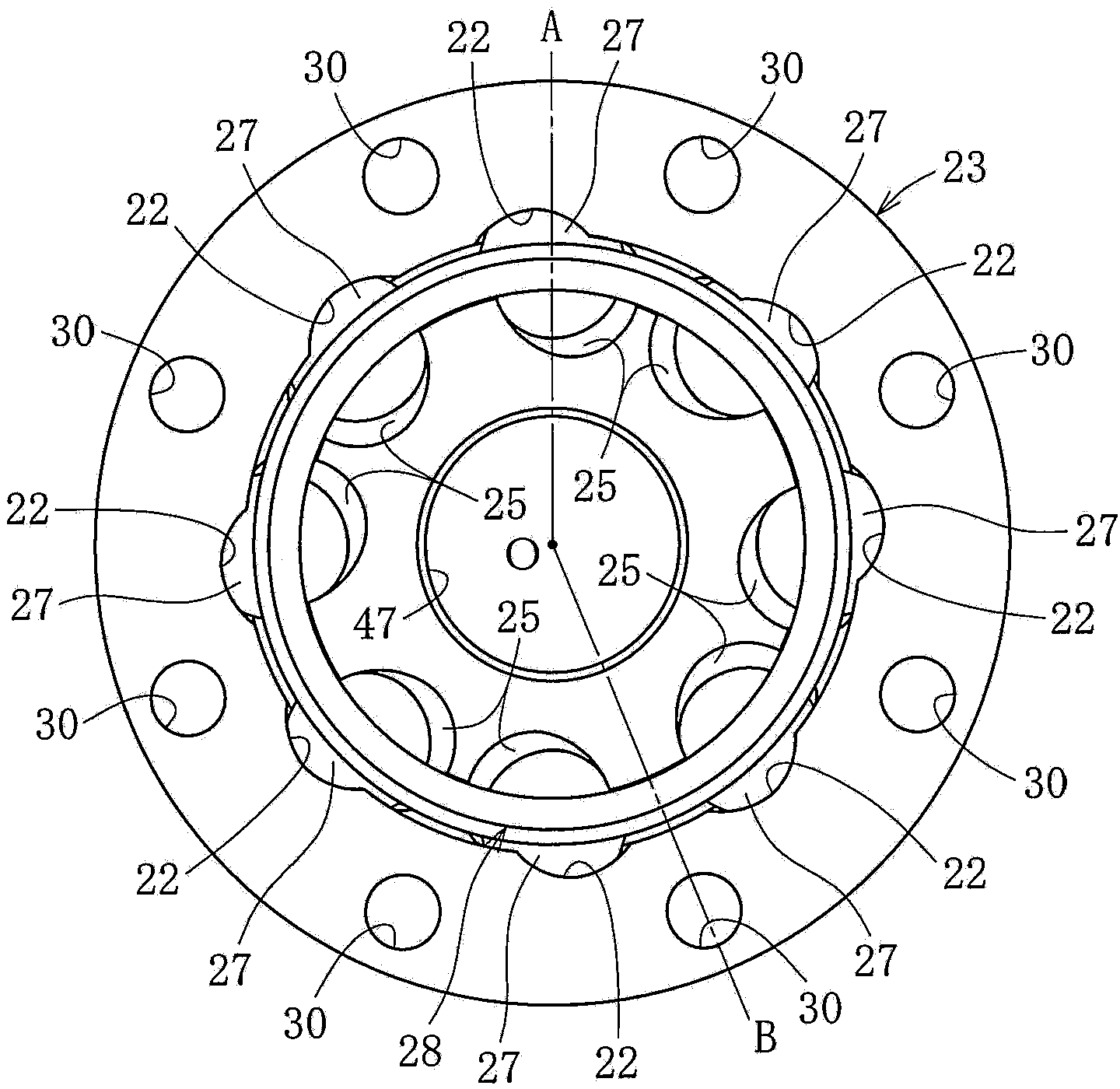
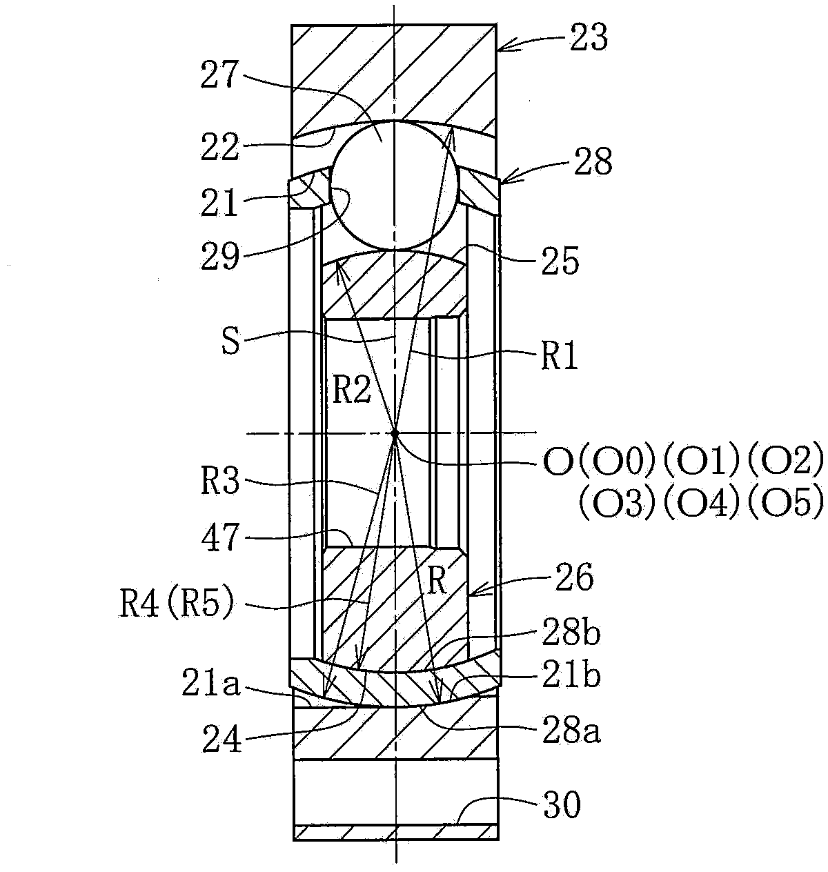
[0058] Below, based on Figure 1 to Figure 22 , to describe the embodiment of the present invention.

[0059] Such as Figure 1 ~ Figure 3 As shown, the fixed constant velocity universal joint according to the first embodiment of the present invention includes: an outer joint member 23 having a plurality (eight) of raceway grooves 22 axially formed on an inner diameter surface 21; The inner joint member 26 with a plurality of (eight) raceway grooves 25 formed in the axial direction; A plurality (eight) of torque transmission balls 27 on the track; and a cage 28 that holds the torque transmission balls 27 and is interposed between the inner diameter surface 21 of the outer joint member 23 and the outer diameter surface 24 of the inner joint member 26 .

[0060] A female spline 45 is formed on the inner diameter surface of the hole 47 of the inner joint member 26, and a male spline 46 of the shaft 31 is fitted into the hole 47 of the inner joint member 26. The female spline 4...


PUM


Abstract

Provided is a fixed type constant velocity universal joint capable of suppressing heat generation under high load and during high-speed rotation to improve durability, and suppressing a contact resistance between a cage and inner and outer joint members to improve the constant velocityproperty. An axial offset amount of a curvature center of each track groove (22) of an outer joint member (23) and an axial offset amount of a curvature center of each track groove (25) of an inner joint member (26) are zero. Track grooves (22a, 22b) of the outer joint member (23) are formed alternately in a circumferential direction to be inclined in mutually opposite directions with respect to an axis, and track grooves (25a, 25b) of the inner joint member (26) are formed alternately in the circumferential direction to be inclined in mutually opposite directions with respect to the axis. An outer surface (24) of the inner joint member (26) is formed into a spherical surface (21b) which is held in slide-contact with an inner spherical surface (28b) of a cage (28). An inner surface (21) of the outer joint member (23) is formed into a cylindrical surface (21a).

Description

technical field [0001] The present invention relates to, for example, a constant velocity universal joint used in a power transmission system of an automobile or various industrial machines. Background technique [0002] In a 4WD vehicle (four-wheel drive vehicle) or an FR vehicle (rear-wheel drive vehicle), a propeller shaft is used to transmit rotational driving force from a transmission to a differential. In such a propeller shaft, when a vehicle collides, the propeller shaft is in a supported state, and the impact force generated by the vehicle increases. Therefore, the pipe portion connected to the constant velocity universal joint is bent in a horizontal V shape, and this bent portion may enter the vehicle interior. [0003] Therefore, conventionally, various mechanisms for absorbing axial displacement generated at the time of collision have been proposed (Patent Document 1 to Patent Document 3). [0004] In Patent Document 1, the tube shaft is connected to the outer...

Claims


Application Information

Patent Timeline
Patent Type & Authority Patents(China)
IPC IPC(8): F16D3/2245F16D3/84
CPCF16D2003/22313F16D2003/2232F16D3/2245F16D3/845F16D2003/22309F16D3/224
Inventor 藤尾辉明
Owner NTN CORP
Learn More