
Recoverable protective circuit of boosting LED (light emitting diode) driving power supply and design method of recoverable protective circuit

A technology for LED driving and protection circuits, which is applied in the direction of protection against overvoltage, protection against overcurrent, lamp circuit layout, etc., and can solve problems such as circuit repeated startup in the fuse open circuit protection circuit

Active Publication Date: 2012-07-25
SHANGHAI INST OF TECHNICAL PHYSICS - CHINESE ACAD OF SCI +1
View PDF4 Cites 8 Cited by
  • Summary
  • Abstract
  • Description
  • Claims
  • Application Information

AI Technical Summary

Problems solved by technology

[0005] The purpose of the present invention is to solve the technical defects of the short-circuit protection circuit and open-circuit protection circuit of the existing boost LED drive power supply, especially to solve the problem of needing to replace the damaged fuse in the short-circuit protection circuit and the problem of repeated start-up of the circuit in the open-circuit protection circuit

Method used


Image

  • Recoverable protective circuit of boosting LED (light emitting diode) driving power supply and design method of recoverable protective circuit
  • Recoverable protective circuit of boosting LED (light emitting diode) driving power supply and design method of recoverable protective circuit
  • Recoverable protective circuit of boosting LED (light emitting diode) driving power supply and design method of recoverable protective circuit

Examples


Embodiment Construction

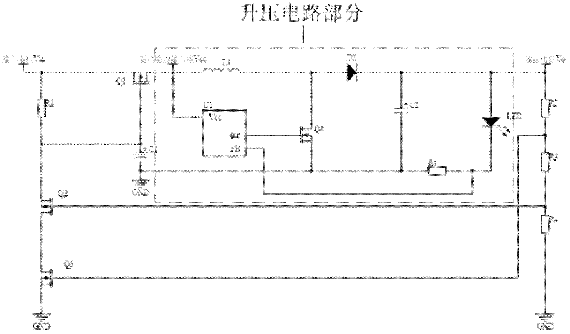
[0029] attached figure 2 A schematic circuit diagram of an embodiment of the protection circuit provided by the present invention is shown. Note that, for brevity, figure 2 Only the main part of the step-up LED driver power supply is marked.

[0030] attached figure 2 In addition to the short-circuit protection circuit part of the present invention, the other components are: U1 is a power control chip, L1 is an inductor, Q4 is a power switch tube, D1 is an output rectifier diode, C2 is an output capacitor, and Rs is a current sampling resistor.

[0031] attached figure 2The input voltage of the medium-boost LED driver power supply is 7V, the output voltage is 10V, and the output current is 350mA.

[0032] The value of the inductor L1 is L 2 =15uH, the capacitance value of capacitor C2 is c 2 =100uF, the resistance value of resistor Rs is r s = 0.15Ω. The maximum output voltage voltage V max =12V. Select P-channel field effect transistors Q1 and Q2 as IRF4905, and...


PUM


Abstract

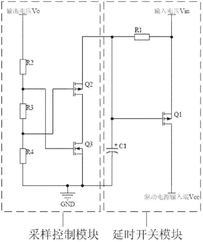
The invention discloses a recoverable protective circuit of a boosting LED (light emitting diode) driving power supply and a design method of the recoverable protective circuit, aiming at realizing short circuit protection and open circuit protection, wherein the protective circuit comprises a sampling control module and a time delay switch module. According to the invention, the voltage of an output end of the boosting LED driving power supply is directly used as a trigger signal, so that open circuit and short circuit states of the circuit can be responded accurately. According to the protective circuit, the purpose that the connection between an input voltage and an LED driving power supply input end is powered off rapidly when the open circuit or short circuit happens to the LED driving power supply output end, and the purpose that the LED driving power supply is prevented from being restarted, are achieved in a way that the connection between the input voltage and the LED driving power supply input end is controlled; so that the protective circuit needs no fuse and can be restarted after fault elimination is performed; and meanwhile, the protective circuit has the characteristics of simple structure, convenience in regulation, low energy consumption, low cost and the like.

Description

technical field [0001] The invention relates to a protection circuit. In particular, the invention relates to a protection circuit and a design method of a boost LED driving power supply. Background technique [0002] With the application of LED lighting more and more widely, users have higher and higher requirements for the life of LED lighting lamps, and higher reliability requirements for LED driving power supply. And this requires the LED drive power supply to be able to protect itself and the safety of the load equipment under various abnormal conditions. Among them, the boost circuit has been widely used as a simple and practical LED driving power supply circuit, and short circuit protection and open circuit protection are also its indispensable protection functions. When the output terminal of the boost LED driver power supply is short-circuited, the input voltage is directly connected to the output terminal, and the output current rises sharply; when the output ter...

Claims


Application Information

Patent Timeline
Patent Type & Authority Applications(China)
IPC IPC(8): H05B37/02H02H3/08H02H3/20
Inventor 董硕张涛陈苏广刘石神袁士东
Owner SHANGHAI INST OF TECHNICAL PHYSICS - CHINESE ACAD OF SCI
Learn More