Radio frequency power amplifier system having waveband switching function
A radio frequency power amplifier and band switching technology, which is applied in high frequency amplifiers, power amplifiers, and improved amplifiers to improve efficiency. Product miniaturization development and other issues, to achieve high-speed communication and high-speed data processing, simplify control and detection modes, and achieve the effect of configuration and optimization
- Summary
- Abstract
- Description
- Claims
- Application Information
AI Technical Summary
Problems solved by technology
Method used
Image


Examples
Embodiment 1
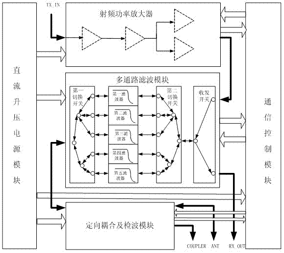
[0034] Such as figure 1 As shown, this example provides a radio frequency power amplifier system with band switching, including:
[0035] DC boost power module;
[0036] A radio frequency power amplifier, which inputs a radio frequency signal to be amplified and is connected to the DC boost power module;
[0037] The multi-channel filter module is used to select different channels for filtering and output radio frequency signals, which are respectively connected to the DC boost power supply module and the radio frequency power amplifier;
[0038] The directional coupling and detection modules are respectively connected with the DC boost power supply module and the multi-channel filter module;
[0039] The communication control module is powered by the DC boost power supply module and is respectively connected with the radio frequency power amplifier, the multi-channel filter module and the directional coupling and detection module.
[0040] Wherein, the DC boost power module is a DC-DC ...
Embodiment 2
[0046] The difference from Embodiment 1 is that the directional coupling and detection module in this example includes a 40dB directional coupler.
[0047] In terms of production, the production process, indicators and performance of various devices will show certain differences, especially in mass production, there will be more problems. Therefore, the screening of production processes and devices in this example The requirements need to be very strict.
[0048] This example further adopts the above technical features, and its advantage is that it provides a high-power ultra-wideband radio frequency power amplifier system with band switching, which can realize high-speed communication and high-speed data processing, and realize the configuration and optimization of radio frequency signal parameters. Communication with other components simplifies the control and detection mode of this example. On this basis, the directional coupling and detection module includes a 40dB directional ...
Embodiment 3
[0050] The difference from Embodiment 1 is that the multi-path filter module in this example includes a first switch, a filter, a second switch, and a transceiver switch that are connected in sequence.
[0051] This example further adopts the above technical features, and its advantage is that it provides a high-power ultra-wideband radio frequency power amplifier system with band switching, which can realize the digital predistortion processing for the transplantation of the radio frequency power amplifier, and realize high-speed communication and high-speed data processing. The control and detection mode is simplified, and the volume is small. On this basis, the multi-channel filter module includes a first switch, a filter, a second switch, and a transceiver switch connected in sequence. The first switch, the second switch The second switch and the transceiver switch adopt diodes, and the filter can adopt a small-sized LC filter, which realizes band switching while controlling t...
PUM
| Property | Measurement | Unit |
|---|---|---|
| Average power | aaaaa | aaaaa |
| Peak power | aaaaa | aaaaa |
Abstract
Description
Claims
Application Information
 - R&D
- Intellectual Property
- Life Sciences
- Materials
- Tech Scout
- Unparalleled Data Quality
- Higher Quality Content
- 60% Fewer Hallucinations
Browse by: Latest US Patents, China's latest patents, Technical Efficacy Thesaurus, Application Domain, Technology Topic, Popular Technical Reports.
© 2025 PatSnap. All rights reserved.Legal|Privacy policy|Modern Slavery Act Transparency Statement|Sitemap|About US| Contact US: help@patsnap.com