
Surface-mounted temperature relay

A temperature relay, mounted technology, applied in the direction of thermal switch components, etc., can solve the problem that the temperature relay cannot meet the demand, and achieve the effect of good insulation and voltage resistance performance, convenient installation, and improved welding quality.

Inactive Publication Date: 2014-05-28
中国电子科技集团公司第四十研究所
View PDF5 Cites 0 Cited by
  • Summary
  • Abstract
  • Description
  • Claims
  • Application Information

AI Technical Summary

Problems solved by technology

Therefore, the existing temperature relays can no longer meet the needs of modern military equipment

Method used


Image

  • Surface-mounted temperature relay
  • Surface-mounted temperature relay
  • Surface-mounted temperature relay

Examples


Embodiment 1

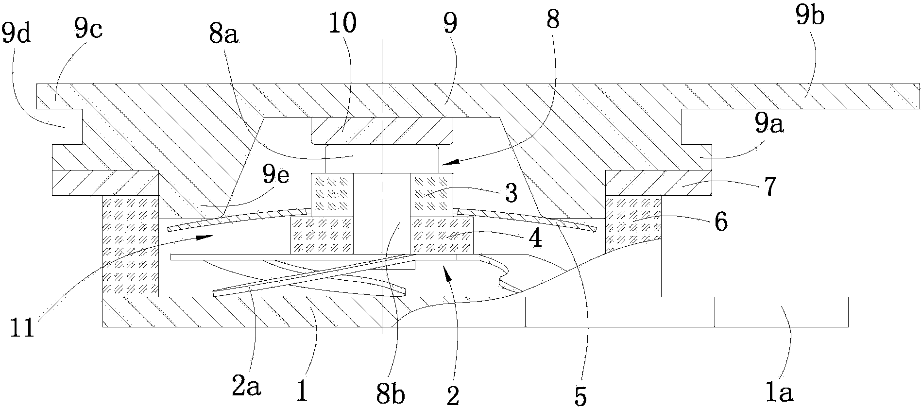
[0024] see figure 1 , figure 2 :

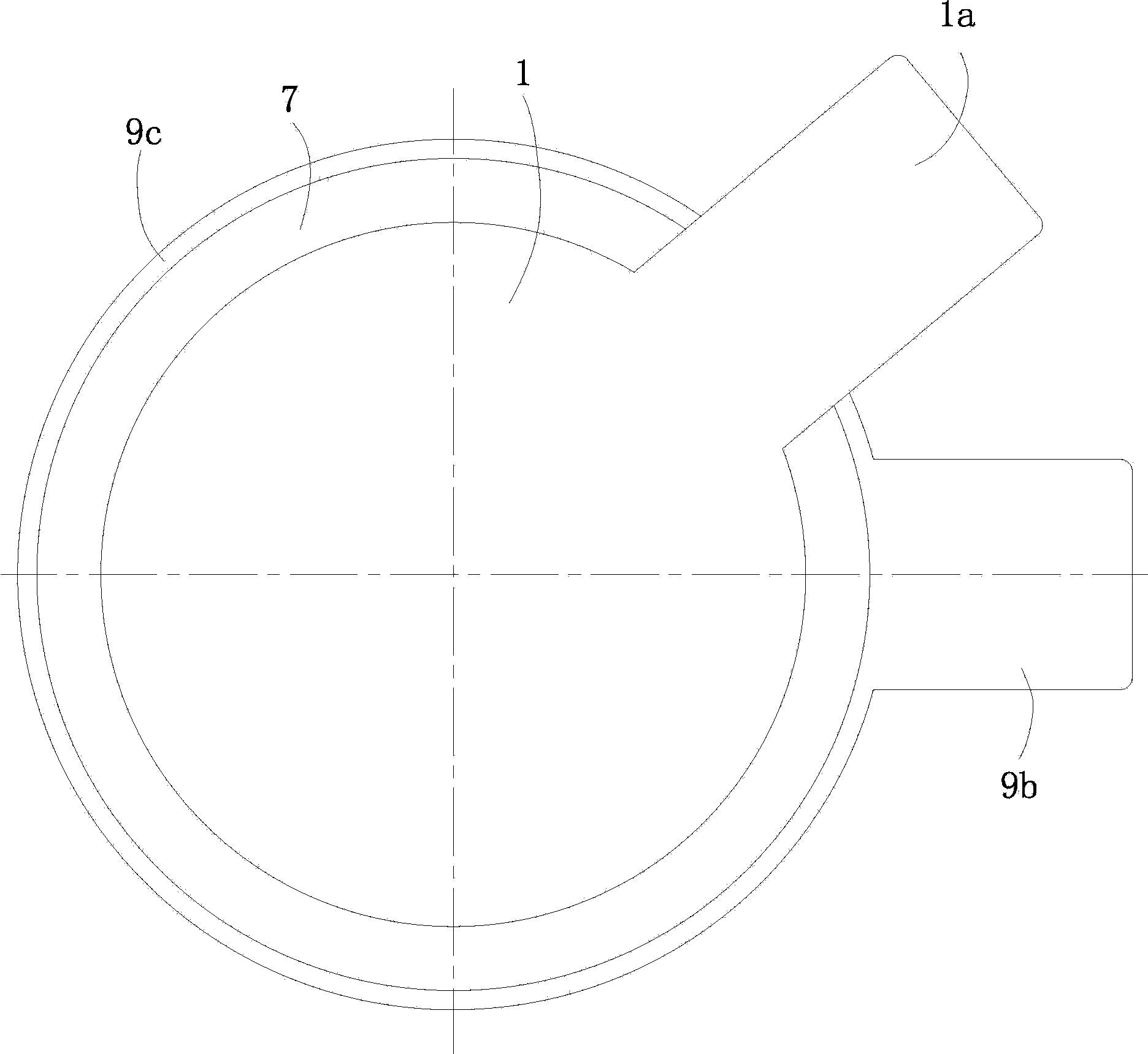
[0025] The relay includes a circular horizontal upper cover 9, a circular horizontal static contact 10, a movable contact 8, a disc-shaped bimetal 5, a circular elastic movable reed 2, a shell with an open upper end and a closed lower end, and an upper cover 9. The inner central area of ​​the top wall is welded with the static contact 10, the upper part of the side wall of the upper cover 9 has a first flange 9c and a first lug 9b extending horizontally outward is arranged through the first flange 9c, and the bimetallic strip 5 The central area has a circular hole ( figure 1 hole key numbers not shown).

[0026] The shell includes a horizontal welding sheet 7, a vertical ceramic metallization isolation cylinder 6, and a horizontal bottom plate 1 welded up and down in sequence, and a circular perforation ( figure 1 The part number of the perforation is not shown in the figure), the upper and lower ends of the isolation cylinder 6 are open...

Embodiment 2

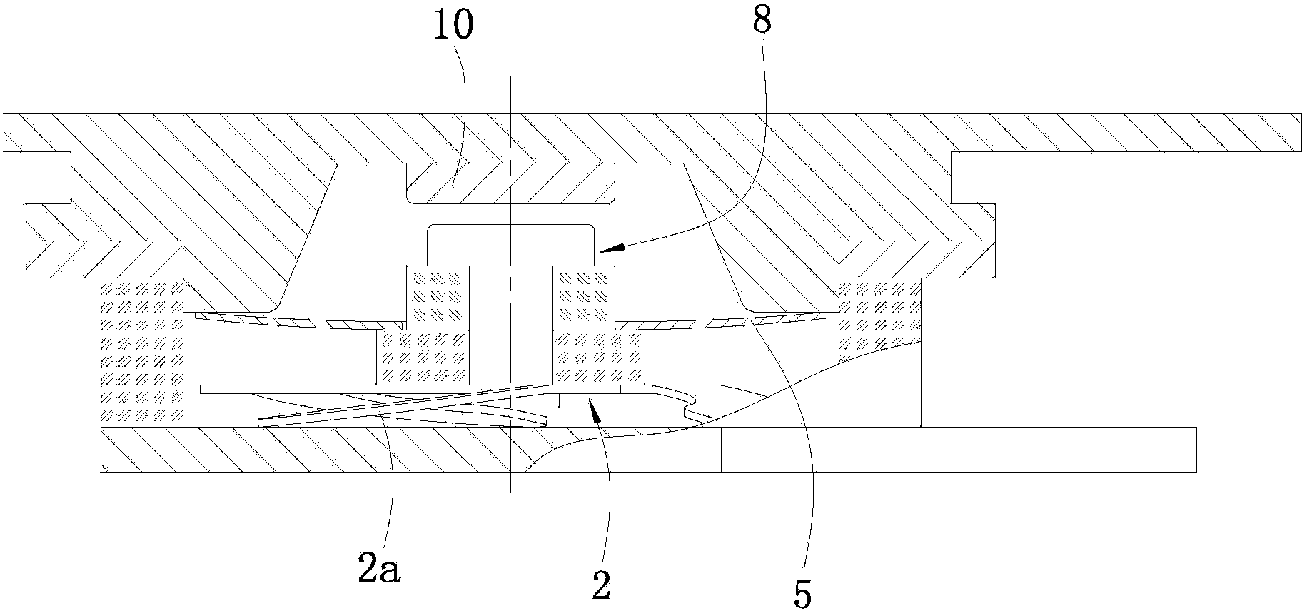
[0036] see image 3 :

[0037] It should be noted that the difference between this embodiment and the first embodiment is only that the bending direction of the bimetal 5 makes the upper end of the movable contact 8 and the static contact 10 in a non-contact state. The rest of the specific structure of this embodiment is the same as that of Embodiment 1, so the rest of the specific structure of this embodiment will not be repeated here.

[0038] Under normal conditions, the upper end of the moving contact 8 and the static contact 10 are in a non-contact state, the relay is in the disconnected state (it is a normally open contact temperature relay), and the moving reed 2 is in a compressed state. When the relay When the sensed temperature meets the operating conditions, the bimetal 5 turns upwards, and under the action of the tension released by the moving reed 2, the moving contact 8 is pushed upwards, and the moving contact 8 and the static contact 10 change from the disconn...


PUM


Abstract

The invention discloses a surface-mounted temperature relay, wherein an outer shell of the surface-mounted temperature relay comprises welding sheets, a ceramic metallic insulation drum and a base plate which are sequentially welded on the outer shell up and down, wherein the lower part of the side wall of an upper cover is provided with a second flanging, and the lower end of the upper cover is provided with a protrusion part; the protrusion part extends into the insulation drum through penetration holes of the welding sheets; after the second flanging and the welding sheets are overlapped up and down, laser welding is carried out; the sum of the thicknesses of the second flanging and the welding sheets is 0.5mm; the upper cover, the welding sheets, the insulation drum and the base plate form a chamber in an airtight-level seal state; a static contact, a moving contact, a butterfly-shaped dual-metal sheet and an elastic moving spring are arranged in the chamber; the lower end of a vertical column of the moving contact and the central region of the moving spring are riveted; a first ceramic block and a second ceramic block are sleeved on the vertical column; after the first ceramic block and the dual-metal sheet are sleeved inside and outside, the dual-metal sheet is loaded on the upper side of the ceramic block, and the dual-metal sheet and the moving spring are in a non-contact state; the dual-metal sheet is in contact with the protrusion part; and the bending direction of the dual-metal sheet enables the moving contact and the static contact to be contacted, or enables the moving contact and the static contact to be in a non-contact state. The ratio of the width to the height of the relay is (3.0-3.6) to 1. The relay is small in volume, is light in weight, is convenient to install, and is reliable in motion.

Description

technical field [0001] The invention relates to a temperature relay, in particular to a surface mounted temperature relay. Background technique [0002] At present, the existing temperature relays have large volume, poor sealing welding quality and reliability, and poor environmental adaptability (such as: anti-vibration, anti-shock, etc.). With the development of airborne equipment towards miniaturization, the temperature relay is also developing towards small size, miniaturization and high reliability. Therefore, the existing temperature relays can no longer meet the needs of modern military equipment. Contents of the invention [0003] The technical problem to be solved by the present invention is to provide a surface-mounted temperature relay with small volume, light weight, convenient installation and reliable operation. [0004] In order to solve the above-mentioned technical problems, the present invention provides a surface-mounted temperature relay, which includ...

Claims


Application Information

Patent Timeline
Patent Type & Authority Patents(China)
IPC IPC(8): H01H37/02H01H37/52
Inventor 罗元春刘超徐奎马玉梅刘秀梅卓超
Owner 中国电子科技集团公司第四十研究所
Learn More