Accelerated loading test device for small full-size asphalt pavement
An asphalt pavement and accelerated loading technology, which is applied in the direction of applying repeated force/pulsation force to test the strength of materials, can solve the problems of huge size, complicated operation process, and inability to accurately simulate the actual stress state of asphalt pavement, and achieve good economy The effect of sex and low cost
- Summary
- Abstract
- Description
- Claims
- Application Information
AI Technical Summary
Problems solved by technology
Method used
Image
Examples
specific Embodiment approach 1
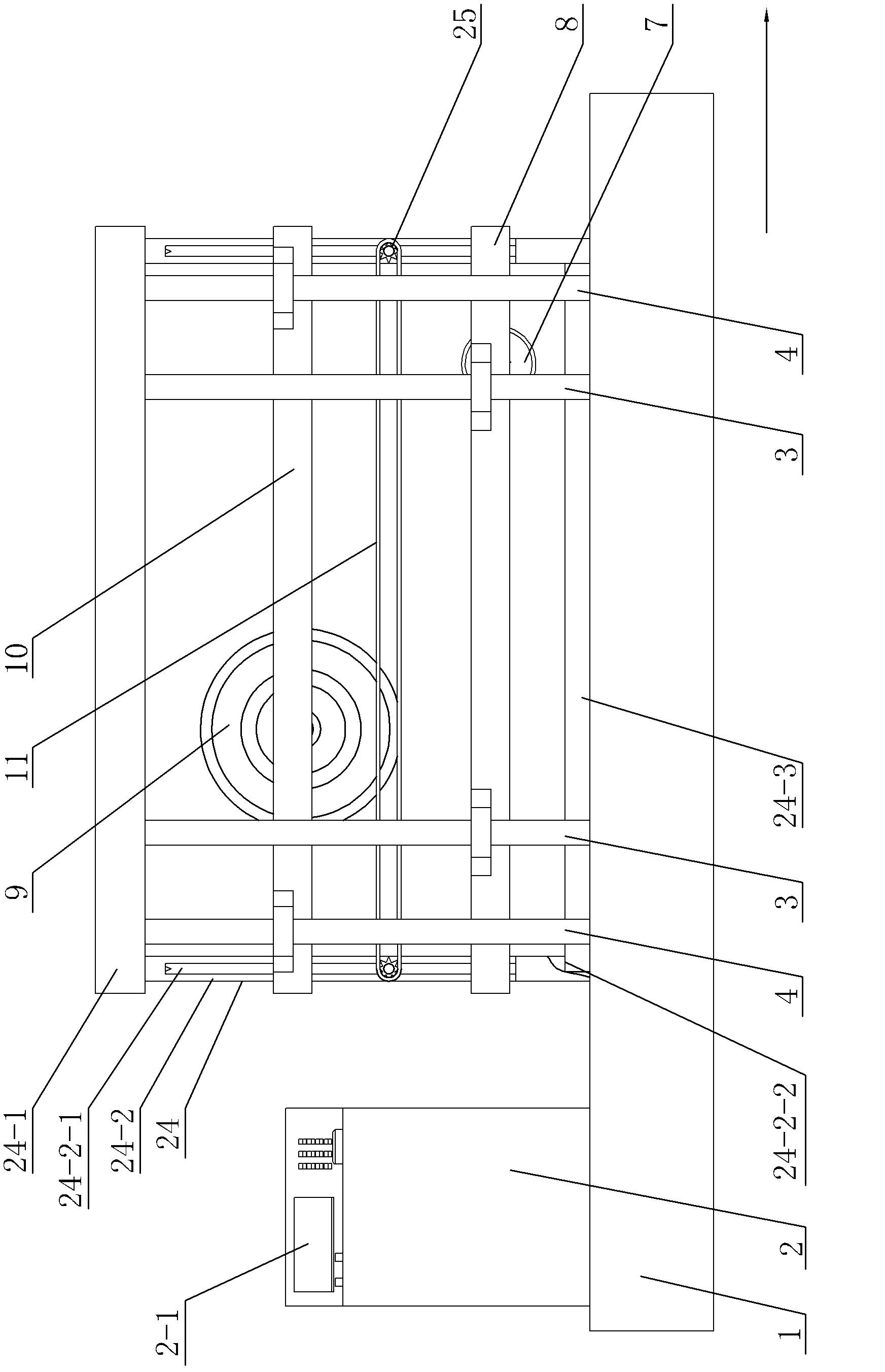
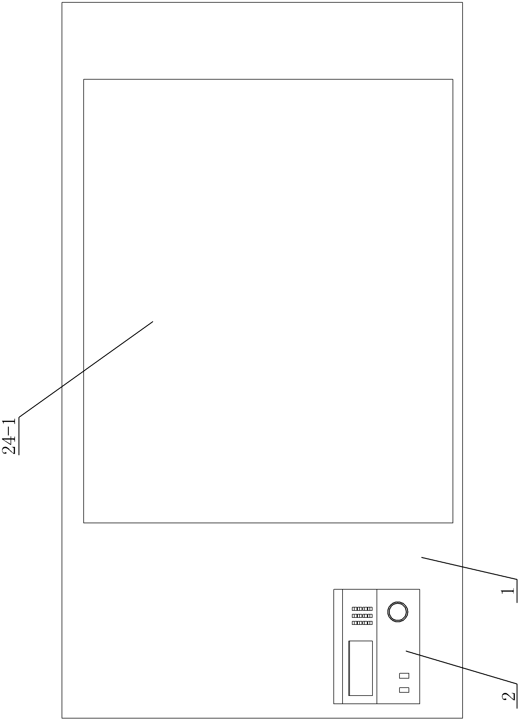
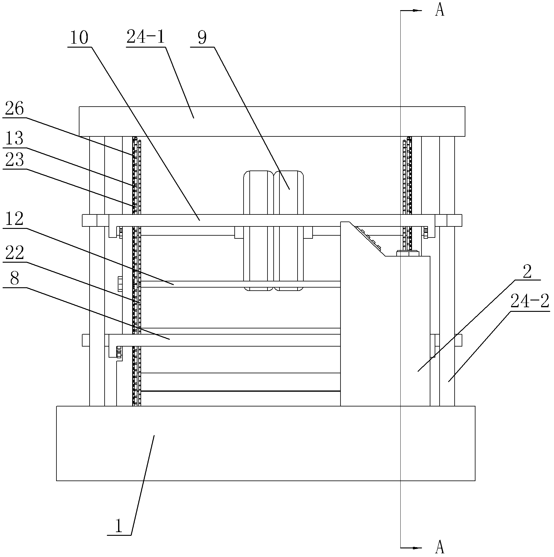
[0017] Specific implementation mode one: combine Figure 1-Figure 8 Explain, the small-sized asphalt pavement accelerated loading test device of this embodiment includes a base 1, a console 2, a frame 24, a rolling steel wheel 7, a rectangular frame steel wheel loading beam 8, and a loading wheel set 9 , rectangular frame wheel group loading beam 10, two groups of inner oil pressure pumps 3, two groups of outer oil pressure pumps 4, two annular horizontal transmission chains 11, two transmission cross bars 12, eight annular vertical transmission chains 13, eight A driven gear 14, twelve power transmission gears 15, eight driving gears 16, two loading wheel drive gears 17, two rolling steel wheel drive gears 18, two bidirectional motors 20, four drive rods 21 , four transition sprockets 25 and four lifting guide rails 26, eight annular vertical transmission chains 13 include four annular vertical inner transmission chains 22 and four annular vertical outer transmission chains 2...
specific Embodiment approach 2
[0020] Specific implementation mode two: combination figure 1 To illustrate, the height of the baffle plate 24-3 in this embodiment is 5cm, 6cm, 7cm, 10cm or 12cm. It can be flexibly adjusted according to user-designed pavement structural layer thickness and test requirements. Others are the same as in the first embodiment.
specific Embodiment approach 3
[0021] Specific implementation mode three: combination figure 1 , Figure 3 ~ Figure 6 Explain that each group of internal hydraulic pumps 3 in this embodiment includes two internal hydraulic pumps, and among the four supporting legs 24-2, a The hydraulic pump 3 in the group and the rectangular steel wheel loading beam 8 are driven to move up and down by the plunger of the hydraulic pump 3 in the two groups, and the pump body of the hydraulic pump 3 in the two groups is fixed in the base 1 . The purpose of designing like this is to make the rectangular steel wheel loading beam 8 move up and down steadily. Others are the same as in the first or second embodiment.
PUM
| Property | Measurement | Unit |
|---|---|---|
| height | aaaaa | aaaaa |
| diameter | aaaaa | aaaaa |
Abstract
Description
Claims
Application Information
 - R&D
- Intellectual Property
- Life Sciences
- Materials
- Tech Scout
- Unparalleled Data Quality
- Higher Quality Content
- 60% Fewer Hallucinations
Browse by: Latest US Patents, China's latest patents, Technical Efficacy Thesaurus, Application Domain, Technology Topic, Popular Technical Reports.
© 2025 PatSnap. All rights reserved.Legal|Privacy policy|Modern Slavery Act Transparency Statement|Sitemap|About US| Contact US: help@patsnap.com


