
Central air-conditioning system and control method thereof

A central air-conditioning system and thermostat technology, which is applied in heating systems, central heating components, heating and ventilation control systems, etc., can solve problems such as unrealistic energy deployment, terminal output oscillation, and increased refrigerant flow, etc., to achieve reduction The amount of circulating water in the system, the effect of solving the problem of large pressure difference at the proximal end and high heat exchange efficiency

Active Publication Date: 2012-07-25
谭仲禧
View PDF8 Cites 15 Cited by
  • Summary
  • Abstract
  • Description
  • Claims
  • Application Information

AI Technical Summary

Problems solved by technology

[0002] The main purpose of setting up a central air-conditioning system is to obtain a comfortable indoor environment. Common central air-conditioning systems mostly use different programs to distribute and distribute circulating water pipelines. The following problems often occur during use: 1. It cannot always be installed in all The required temperature is obtained in the end room, especially when the local end heat load changes, it cannot be adjusted to the required temperature in time; 2. Even if the cooling or heat output device has sufficient capacity, the system still There will be uneven heating and cooling; 3. When the room temperature reaches the required value, the output at the end will continue to oscillate; 4. Water hammer sounds often appear in rooms near the main water supply pipe; 5. Sometimes there will be excessive noise in the room. cold or annoying draft sensation
[0008] When a flow balance valve is installed at the end of the system, the setting value of the valve control is selected according to the design load of the end unit, that is, the maximum flow of the flow balance valve is the flow rate of the end unit under the maximum design load condition. In actual use, the flow balance valve mainly plays the role of flow limitation. Once the load demand of the terminal unit exceeds the original design maximum load, it is impossible to increase the refrigerant flow through the terminal unit, resulting in a decrease in comfort, which cannot be realized. Allocation of energy in an area

Method used


Image

  • Central air-conditioning system and control method thereof
  • Central air-conditioning system and control method thereof
  • Central air-conditioning system and control method thereof

Examples


Embodiment 1

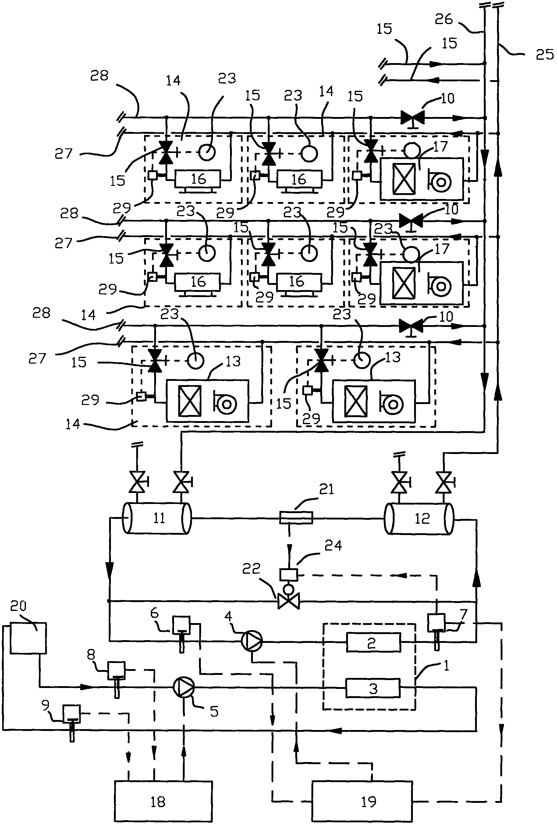
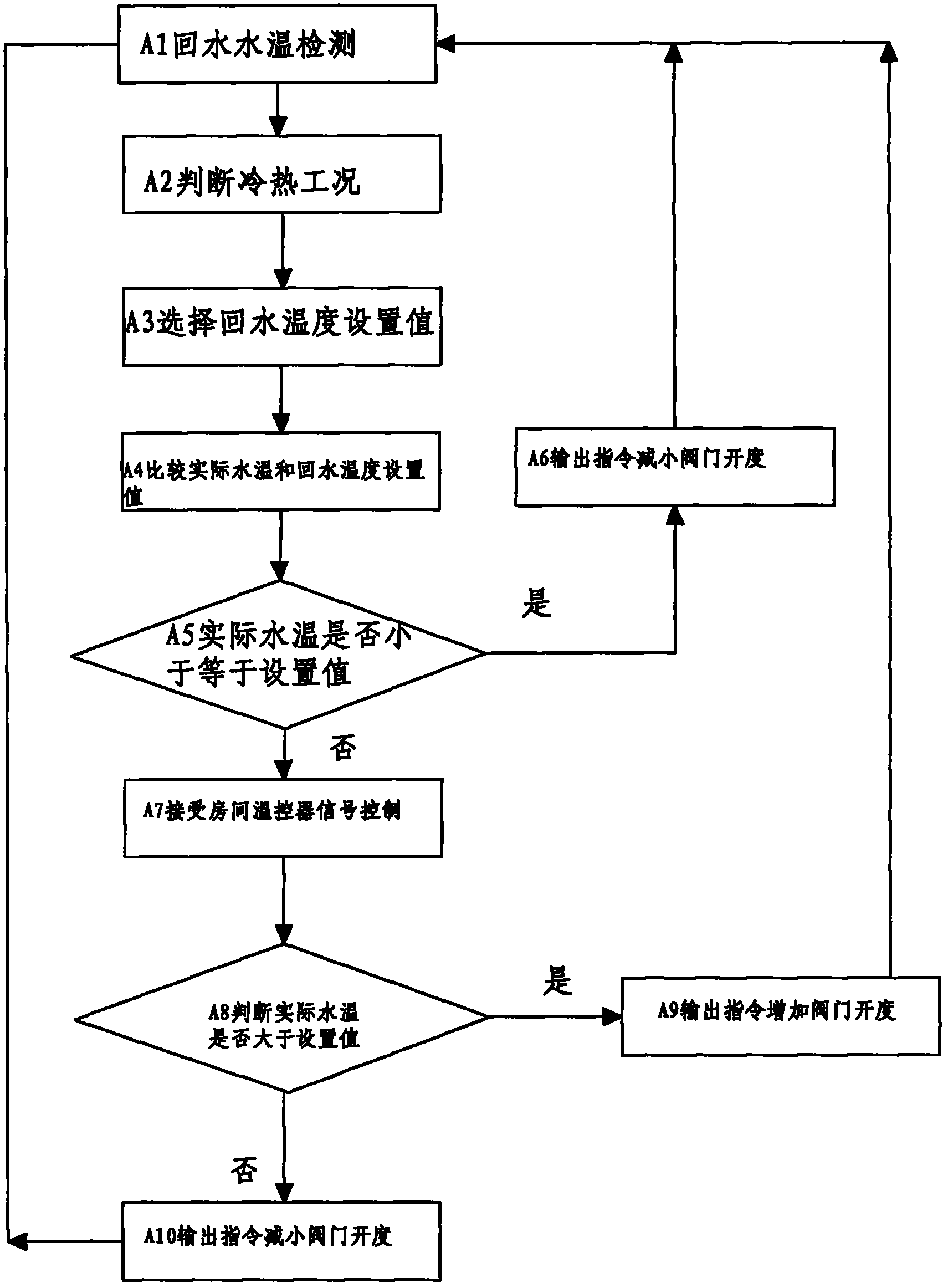
[0035] refer to figure 1 , a central air-conditioning system, comprising a refrigerating unit 1, a cooling water circuit, a cooling water pump 5 arranged on the cooling water circuit, a cooling water pump frequency converter 18, a circulating water circuit, a circulating water pump 4 arranged on the circulating water circuit, a circulating water pump Frequency converter 19, several circulating water branches arranged in parallel on the circulating water circuit, and thermostats 23, terminal fan coils 16, fresh air unit 17 and air handling unit 13 arranged in each room 14, wherein the circulating water circuit includes The main water inlet pipe 25 and the water return main pipe 26, the circulating water branch includes the water inlet branch pipe 27 and the water return branch pipe 28, and the terminal fan coil unit 16, the fresh air unit 17 and the air handling unit 13 are respectively arranged in parallel on the circulating water branch road. The return water branch pipes 28 ...

Embodiment 2

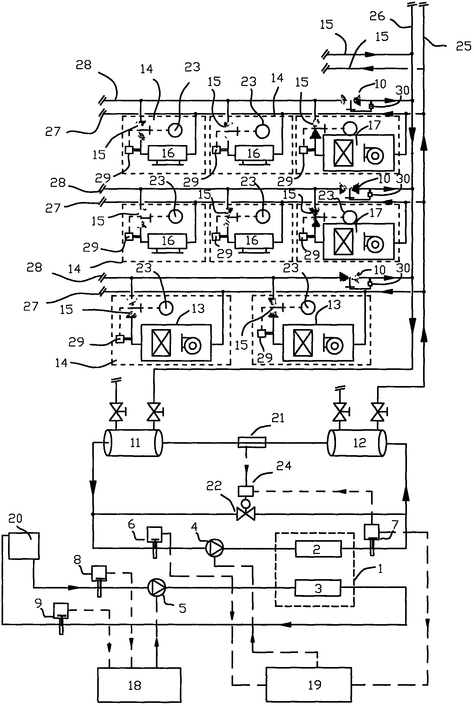
[0050] refer to image 3 , a central air-conditioning system, comprising a refrigerating unit 1, a cooling water circuit, a cooling water pump 5 arranged on the cooling water circuit, a cooling water pump frequency converter 18, a circulating water circuit, a circulating water pump 4 arranged on the circulating water circuit, a circulating water pump Frequency converter 19, several circulating water branches arranged in parallel on the circulating water circuit, and thermostats 23, terminal fan coils 16, fresh air unit 17 and air handling unit 13 arranged in each room 14, wherein the circulating water circuit includes The main water inlet pipe 25 and the water return main pipe 26, the circulating water branch includes the water inlet branch pipe 27 and the water return branch pipe 28, and the terminal fan coil unit 16, the fresh air unit 17 and the air handling unit 13 are respectively arranged in parallel on the circulating water branch road. The return water branch pipes 28 ...

Embodiment 3

[0065] refer to Figure 5 , is another central air-conditioning system, comprising a refrigeration unit 1, a cooling water circuit, a cooling water pump 5 arranged on the cooling water circuit, a cooling water pump frequency converter 18, a circulating water circuit, a circulating water pump 4 arranged on the circulating water circuit, Circulating water pump frequency converter 19, several circulating water branches arranged in parallel on the circulating water circuit, thermostats 23 arranged in each room 14, terminal fan coil unit 16, fresh air unit 17 and air handling unit 13, in which the circulating water The loop includes a water inlet main pipe 25 and a water return main pipe 26. The circulating water branch includes an inlet water branch pipe 27 and a water return branch pipe 28. The terminal fan coil unit 16, fresh air unit 17 and air handling unit 13 are respectively arranged in parallel on the circulating water branch road. Each of the return water branch pipes 28 i...


PUM


Abstract

The invention discloses a central air-conditioning system and a control method thereof. The central air-conditioning system is characterized in that regional flow balancing valves used for controlling flow of return branch pipes are arranged on the return branch pipes, and energy balancing valves are arranged on return pipes of tail-end fan coilers. The control method of the central air-conditioning system includes: detecting flow in the return branch pipes, adjusting the flow in the return branch pipes to be smaller than or equal to the set flow value of the return branch pipes, detecting the temperature of return water in the return pipes of the tail-end fan coiler, controlling the temperature of the return water in the return pipes of the tail-end fan coiler to be larger than or equal to the set temperature value of the tail-end return water, detecting the room temperature and adjusting openness of the energy balancing valves in a temperature controller. The central air-conditioning system has the advantages that the problem of unevenness of heat caused by static and dynamic imbalance is solved, the central air-conditioning system is more stable, design work quantity is reduced, balance adjustment is more convenient, energy consumption is low and comfortableness is high.

Description

technical field [0001] The invention relates to a central air-conditioning system balance control technology, in particular to a HVAC system water balance control technology. Background technique [0002] The main purpose of setting up a central air-conditioning system is to obtain a comfortable indoor environment. Common central air-conditioning systems mostly use different programs to distribute and distribute circulating water pipelines. The following problems often occur during use: 1. It cannot always be installed in all The required temperature is obtained in the end room, especially when the local end heat load changes, it cannot be adjusted to the required temperature in time; 2. Even if the cooling or heat output device has sufficient capacity, the system still There will be uneven heating and cooling; 3. When the room temperature reaches the required value, the output at the end will continue to oscillate; 4. Water hammer sounds often appear in rooms near the main ...

Claims


Application Information

Patent Timeline
Patent Type & Authority Applications(China)
IPC IPC(8): F24F11/02
CPCF24F11/02F24D11/0214F24D19/1015F24D2220/2027F24F11/83F24F11/85F24F11/84Y02B30/12F25D17/02F25D29/00
Inventor 谭仲禧
Owner 谭仲禧
Learn More