Gear shaft quenching work fixture

A tooling fixture and gear shaft technology, which is applied in the field of quenching tooling fixtures for active cylindrical gear shafts, can solve problems such as easy bending deformation, lack of precision, large deformation, etc., and achieve the effects of eliminating bending deformation, ensuring uniformity, and improving space

Inactive Publication Date: 2012-07-25
江国辉
View PDF3 Cites 2 Cited by
  • Summary
  • Abstract
  • Description
  • Claims
  • Application Information

AI Technical Summary

Problems solved by technology

In order to improve the surface wear resistance, fatigue strength, core toughness, etc. of the gear shaft, carburizing and quenching is usually used, which is easy to bend and deform during quenching, and because the diameter of the driving shaft is usually large, it needs to be hardened more than ordinary The quenching temperature is higher, which will cause greater deformation during quenching and fail to meet the required precision

Method used


Image

  • Gear shaft quenching work fixture
  • Gear shaft quenching work fixture
  • Gear shaft quenching work fixture

Examples


Embodiment Construction

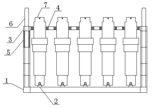
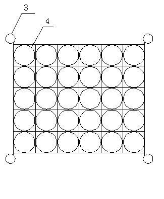
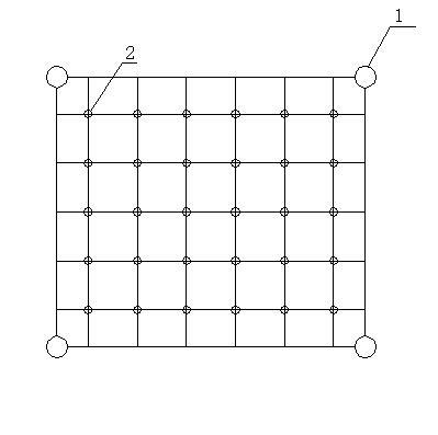
[0010] Such as figure 1 , figure 2 and image 3 As shown, the present invention provides a gear shaft quenching fixture, which includes a lower tray positioning sleeve 1 and an upper tray positioning sleeve 3, both of which are arranged in parallel and are movably installed on the vertical rod group 6, and the vertical rod group 6 is provided with a spacer 5, the spacer 5 is located between the positioning sleeve 3 of the upper feeding tray and the positioning sleeve 1 of the lower feeding tray, and is flexibly connected with the positioning sleeve 3 of the upper feeding tray. By adjusting the spacing sleeve 5, the positioning of the upper feeding tray can be lifted Cover 3, the vertical rod group 6 is made up of four vertical rods, and the four vertical rods are respectively located around the lower tray positioning sleeve 1 and the upper feeding tray positioning sleeve 3. One or more lower tray positioning thimbles 2 are provided on the lower tray positioning sleeve 1, an...


PUM


Abstract

The invention discloses a gear shaft quenching work fixture, which comprises a discharging disc positioning sleeve (1) and a feeding disc positioning sleeve (3). The discharging disc positioning sleeve (1) and the feeding disc positioning sleeve (3) are arranged on a vertical rod group (6) in parallel, one or more discharging disc positioning ejector pins (2) is arranged on the discharging disc positioning sleeve (1), one or more workpiece positioning holes (4) corresponding to the discharging disc positioning ejector pins (2) is arranged on the feeding disc positioning sleeve (3), a shaft workpiece (7) is fixed between each discharging disc positioning ejector pin (2) and the corresponding workpiece positioning hole (4), the bottom of each shaft workpiece (7) is fixed on the corresponding discharging disc positioning ejector pin (2), and the top of each shaft workpiece (7) is fixed in the corresponding workpiece positioning hole (4). The gear shaft quenching work fixture has the advantages that the gear shaft quenching work fixture is convenient in installation, reduces deformation, and improves quenching quality and production efficiency.

Description

technical field [0001] The invention relates to a gear shaft quenching fixture, in particular to a driving cylindrical gear shaft quenching fixture. Background technique [0002] In the process of manufacturing automobile gear shafts, heat treatment is a necessary process. In order to improve the surface wear resistance, fatigue strength, core toughness, etc. of the gear shaft, carburizing and quenching is usually used, which is easy to bend and deform during quenching, and because the diameter of the driving shaft is usually large, it needs to be hardened more than ordinary The higher the quenching temperature, the greater the deformation during quenching, which cannot meet the required precision. Contents of the invention [0003] The invention provides a gear shaft quenching fixture used in quenching. The fixture has the advantages of convenient installation, reduced deformation, improved quenching quality and increased production efficiency. [0004] The present inve...

Claims


Application Information

Patent Timeline
Patent Type & Authority Applications(China)
IPC IPC(8): C21D1/62C21D9/32
Inventor 江国辉
Owner 江国辉
Why Eureka
Try Eureka