Method for welding flange of wind driven generator tower

A technology of wind power generators and welding methods, which is applied to welding equipment, arc welding equipment, and the edge of workpieces, etc., can solve the problems of decreased reliability of tower tubes, affecting connection reliability, and high labor intensity of workers. Low labor intensity, good reliability of flange connection, saving time and labor in production

Inactive Publication Date: 2012-07-25
江苏保龙设备制造有限公司
View PDF4 Cites 5 Cited by
  • Summary
  • Abstract
  • Description
  • Claims
  • Application Information

AI Technical Summary

Problems solved by technology

The above-mentioned existing methods for making inward flanges have the following defects: (1) The inward flange is artificially formed through processing, which is difficult to process, very troublesome to make, time-consuming and laborious, long processing cycle, and labor-intensive for workers , the production quality is poor, and the production cost is high, especially the size of the tower flange is very large, so it is more and more difficult to make the inward flange by this method, and the cost performance is very low; (2) the inward flange produced by the existing method, When the adjacent sections of the tower body are connected by bolts through two flanges, because the joint surfaces of the bolt pairs are not parallel, the connection reliability is affected, and the reliability of the connection of the tower body through the flange is greatly reduced.

Method used


Image

  • Method for welding flange of wind driven generator tower
  • Method for welding flange of wind driven generator tower
  • Method for welding flange of wind driven generator tower

Examples


Embodiment

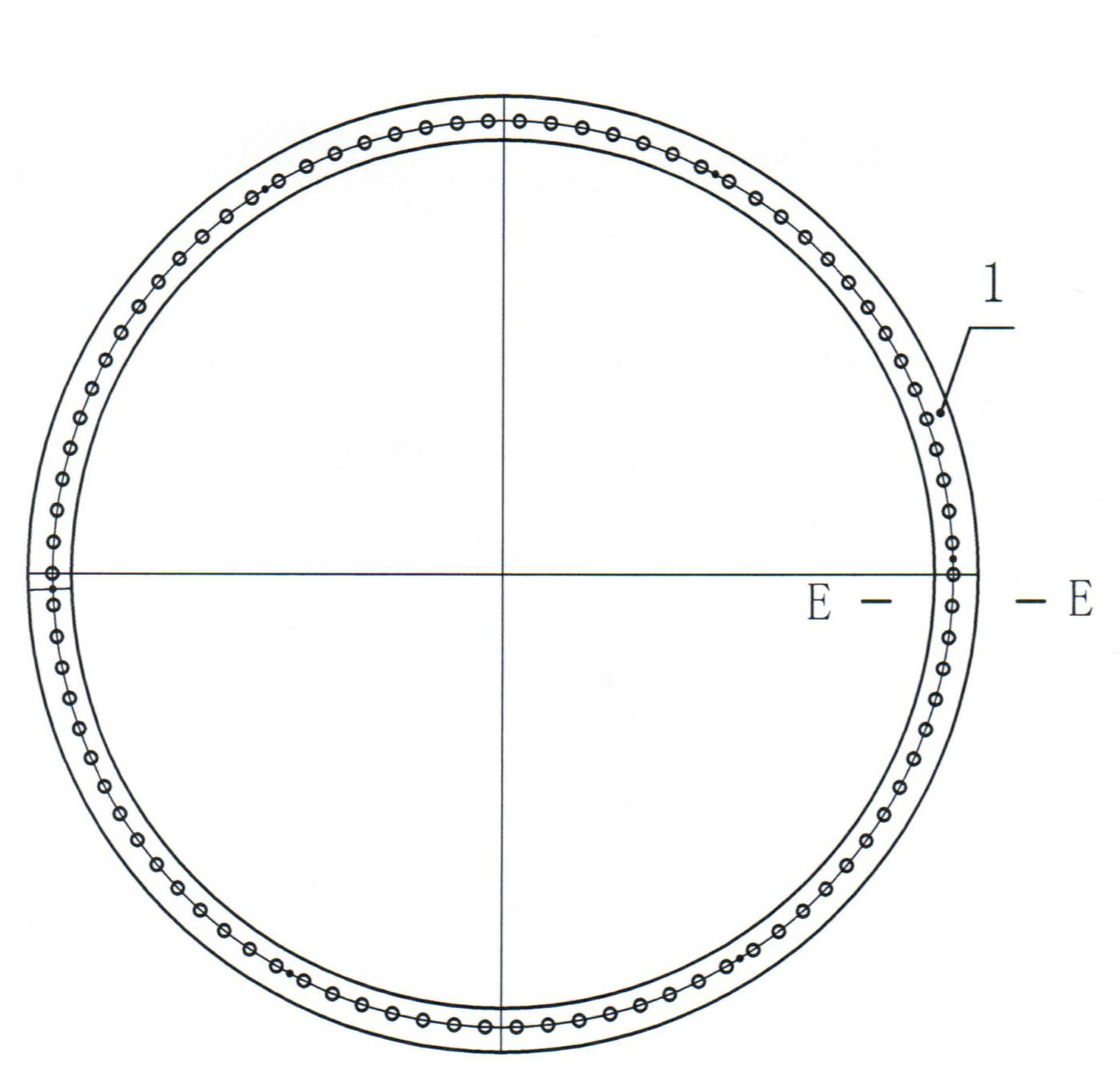
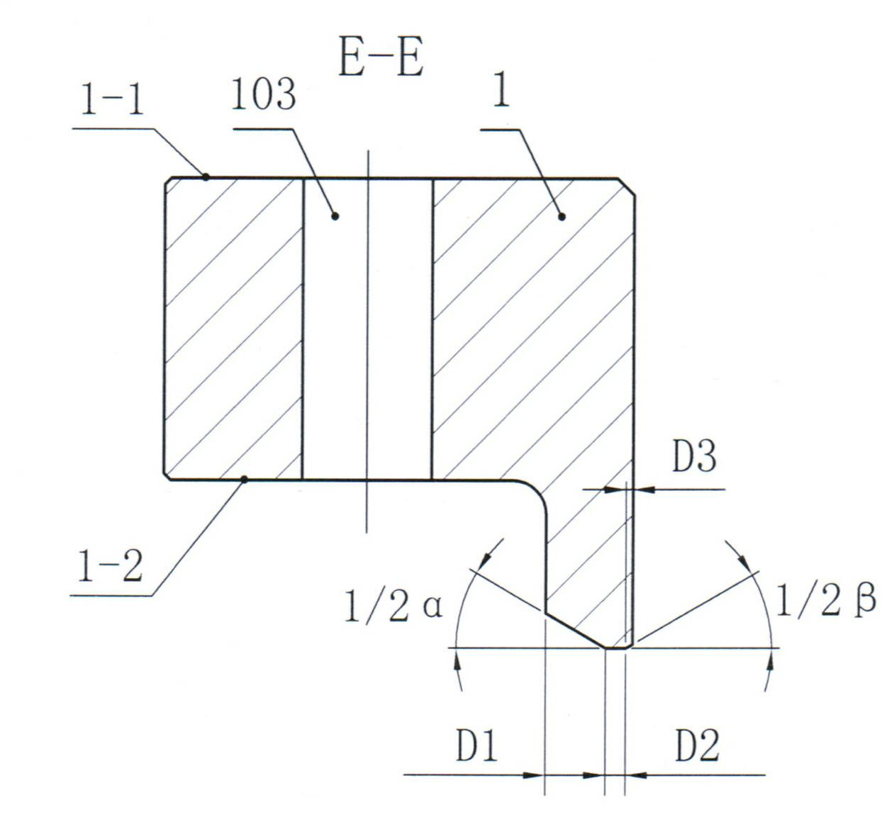
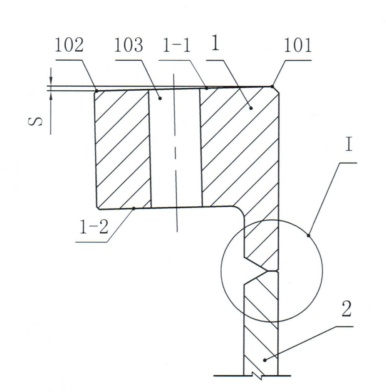
[0036] like Figure 1~5 As shown, a welding method of a wind turbine tower flange is a method of welding an inner flange 1 on each section of the tower body 2 forming the tower to produce an inwardly inclined flange. The steps of the welding method are as follows :

[0037] A. Beveling:

[0038] ——Take the inner flange 1 whose upper surface 1-1 and lower surface 1-2 are parallel, and make a Y-shaped bevel on the inner side of the inner flange 1 and the horizontal end surface 3 of the tower body 2, and make a Y-shaped bevel on the inner side of the horizontal end surface 3 There is a small V-shaped groove on the outside;

[0039] When opening the groove in this step, the horizontal distance of the small V-shaped groove on the outside of the horizontal end surface 3 is D3, and the horizontal distance of the horizontal end surface 3 between the Y-shaped groove and the small V-shaped groove is D2, Y The horizontal distance of the groove is D1, D1>D2>D3. The slope angle α of t...


PUM

PropertyMeasurementUnit
diameteraaaaaaaaaa

Abstract

The invention relates to a method for welding a flange of a wind driven generator tower. The method includes steps: A, beveling grooves: taking an inner flange (1) with an upper surface (1-1) and a lower surface (1-2) which are parallel to each other, beveling a Y-shaped groove on the inner side of a horizontal end surface (3), which is parallel to a tower body (2), of the inner flange, and beveling a small V-shaped groove on the outer side of the horizontal end surface (3); and B, welding at the grooves: welding an outer weld joint (4) at the small V-shaped groove beveled on the outer side of the horizontal end surface (3) at first, then dividing an inner weld joint at the Y-shaped groove into three layers to be welded, welding a first-layer inner weld joint (5) at the bottom of the Y-shaped groove, welding a second-layer inner weld joint (6) on the first-layer inner weld joint, and finally welding a third-layer inner weld joint (7) on the second-layer inner weld joint. The inner inclined flange manufactured by the aid of the method is convenient in manufacture, fine in manufacturing quality and high in cost performance.

Description

technical field [0001] The invention relates to a welding method for a flange of a wind power generator tower. The method of the invention is a welding method for ensuring that the inner flange of the tower tube of the wind power generator and the cylinder body of the tower tube are welded to form an inwardly inclined flange. The invention belongs to the technical field of mechanical equipment manufacturing and processing. Background technique [0002] In the field of wind power generation, wind power generators rely on the wind to drive wind rotors to generate electricity. The wind power generator towers are set under the wind turbine host and wind rotors, supporting the wind turbine host and wind rotors weighing tens of tons. According to the regional distribution of the wind field and the height of the main wind area, the height of the wind turbine tower is also different, and there are various heights such as 55m, 60m, 61.5m, 65m, 70m, and 80m. Among them, the height ...

Claims


Application Information

Patent Timeline
Patent Type & Authority Applications(China)
IPC IPC(8): B23K9/02B23K9/235B23K33/00
Inventor 周伟李树安胡水龙
Owner 江苏保龙设备制造有限公司
Why Eureka
Try Eureka