Optical topology imaging system and method on basis of digital phase locking detection technology

A digital phase-locking, imaging system technology, applied in medical science, diagnostic recording/measurement, sensors, etc., can solve the problems of limited detection area, low measurement signal-to-noise ratio, high price, etc., to improve the measurement area, the system is simple Inexpensive, Inexpensive Effects

Inactive Publication Date: 2012-07-25
TIANJIN UNIV
View PDF5 Cites 11 Cited by
  • Summary
  • Abstract
  • Description
  • Claims
  • Application Information

AI Technical Summary

Problems solved by technology

At present, scientists at home and abroad have done a lot of work in the field of CW-OT technology systems and basic research, and have also achieved many results. The developed practical systems may use highly sensitive photon detection devices, such as photomultiplier tubes (PMTs). ) and avalanche photodiode (APD), which are expensive; or use ordinary photodiode analog measurement methods, the measurement signal-to-noise ratio is not high, and the detection area is greatly limited

Method used


Image

  • Optical topology imaging system and method on basis of digital phase locking detection technology
  • Optical topology imaging system and method on basis of digital phase locking detection technology
  • Optical topology imaging system and method on basis of digital phase locking detection technology

Examples


Embodiment Construction

[0039] The present invention provides an optical topological imaging system based on digital phase-locked detection technology, including a light source part, a detection part, a data acquisition part and a computer, and its principle block diagram is as follows figure 1 As shown, among them,

[0040] Light source part: including two-channel direct digital synthesis (DDS) sinusoidal signal modulator, two lasers with different near-infrared wavelengths (wavelengths are 660nm and 830nm respectively), single-mode fiber, wavelength division multiplexer (two-in-one) and optical switch (5:1). The two-channel direct digital synthesis (DDS) sinusoidal signal modulator is used to output sinusoidal signals of different frequencies (5kHz and 10kHz) to modulate each laser, and the frequency and amplitude of the output signal are controlled and adjusted by the Labview control interface; each laser is controlled by a semiconductor The laser diode (LD) and its corresponding driving componen...


PUM


Abstract

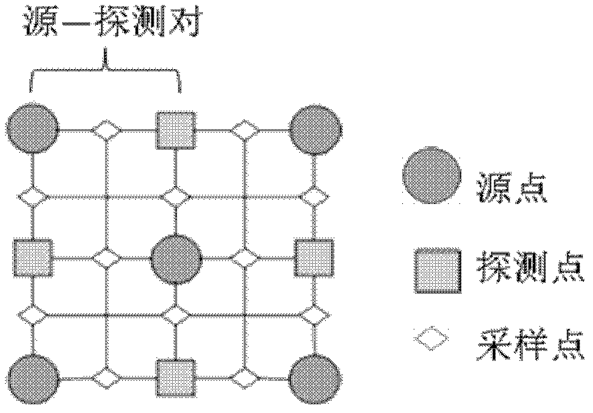
The invention belongs to the field of near-infrared optical tissue imaging, and relates to an optical topology imaging system on the basis of digital phase locking detection technology. The optical topology imaging system comprises a light source, a detection portion, a data acquisition portion and a computer, the light source comprises at least two laser devices capable of generating laser with different near-infrared wavelengths, a multichannel direct digital synthetic sine signal modulator, a single-mode optical fiber and wavelength division multiplexer and a light switch; and the detection portion comprises a plurality of source optical fibers, a plurality of detection optical fibers, source and detection optical fiber distribution patches, four silicon photoelectric diode detectors and a multichannel program control filter amplifier, each source and detection optical fiber distribution patch comprises five source points and four detection points, wherein the five source points of each source and detection optical fiber distribution patch are respectively distributed at the four vertexes and the center of a square, and the four detection points of each source and detection optical fiber distribution patch are distributed at the midpoints of four sides of the corresponding square. The invention also provides a tissue imaging method realized by the aid of the optical topology imaging system. The imaging system is cheap in price, stability of observational measurement imaging is fine, and the measurement area and the accuracy of the system can be improved.

Description

technical field [0001] The invention belongs to the field of near-infrared tissue optical imaging, in particular to an optical topology imaging system based on digital phase-locked detection technology. Background technique [0002] Since the neural activity of the brain has a great influence on the concentration of hemoglobin in the surrounding area, and in the optical window (600nm-900nm) of near-infrared light measurement and treatment, the absorption of light by brain tissue mainly depends on hemoglobin, so it can be passed to the brain. The corresponding functional area of ​​the cortex uses multiple wavelength points in this band for spectral measurement to obtain the concentration change map of oxyhemoglobin and deoxyhemoglobin[1]. Quantitatively obtaining nerve-related functional and physiological information in this way can improve the diagnostic specificity and sensitivity of neurological diseases. [0003] In the past ten years, Optical Topography (OT), developed ...

Claims


Application Information

Patent Timeline
IPC IPC(8): A61B5/00
Inventor 高峰陈琛朱苹苹李娇赵会娟
Owner TIANJIN UNIV
Why Eureka
Try Eureka