
Coaxial through-silicon via

A technology of through-silicon vias and substrates, applied in the direction of semiconductor/solid-state device parts, semiconductor devices, electrical components, etc., can solve problems such as inability to use

Active Publication Date: 2012-07-18
IBM CORP
View PDF5 Cites 22 Cited by
  • Summary
  • Abstract
  • Description
  • Claims
  • Application Information

AI Technical Summary

Problems solved by technology

In addition, furnace oxidation cannot be used after device formation due to its high temperature above 1000°C

Method used


Image

  • Coaxial through-silicon via
  • Coaxial through-silicon via
  • Coaxial through-silicon via

Examples


Embodiment Construction

[0030] The accompanying drawings, which are incorporated in and constitute a part of this specification, illustrate the presently preferred embodiments of the invention and together with the general description given below and the detailed description of the preferred embodiments given below serve to explain the principles of the invention.

[0031] It should be understood that, for simplicity and clarity of illustration, elements shown in the figures have not necessarily been drawn to scale. For example, the dimensions of some of the elements may be exaggerated relative to other elements for clarity.

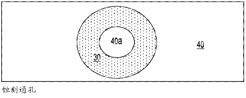
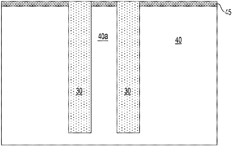
[0032] figure 2 A top view of an annular via 30 etched in a silicon substrate 40 is shown. For the sake of clarity, the structured active layer 45 is not shown in the plan view. The structure is provided with a central pillar 40a defined by etching, made of the same material as the substrate. The width of the central pillar is of the order of 6 μm.

[0033] image 3 yes f...


PUM


Abstract

A through-silicon via (TSV) structure forming a unique coaxial or triaxial interconnect within the silicon substrate 40. The TSV structure is provided with two or more independent electrical conductors 50, 60 insulated from another and from the substrate. The electrical conductors can be connected to different voltages or ground, making it possible to operate the TSV structure as a coaxial or triaxial device. Multiple layers using various insulator materials can be used as insulator, wherein the layers are selected based on dielectric properties, fill properties, interfacial adhesion, CTE match, and the like. The TSV structure overcomes defects in the outer insulation layer that may lead to leakage. A method of fabricating such a TSV structure is also described.

Description

technical field [0001] The present invention relates generally to semiconductor structures and methods of fabrication thereof, and in particular to structures and methods of forming interconnected coaxial and triaxial through-silicon via (TSV) devices. Background technique [0002] A typical electronic system may include different electronic components fabricated for specific functions. Sometimes it is not possible to fabricate these different components on the same substrate because of differences in materials or processing or performance issues. Therefore, it is usually necessary to package separate components and then connect them externally to collectively function as a system. [0003] Typically parts are connected using wire bonding or C4 flip-chip packaging. As microelectronics continue to scale down, the limits of direct scaling may soon be reached. As devices scale, additional problems associated with scaling interconnects arise to accommodate such devices and th...

Claims


Application Information

Patent Timeline
IPC IPC(8): H01L21/768
CPCH01L21/76898H01L2924/0002H01L23/481H01L2924/00H01L21/768H01L23/50
Inventor R.P.沃兰特M.G.法鲁克P.F.芬德伊斯K.S.佩特拉卡
Owner IBM CORP
Learn More