
Comprehensive test system

A comprehensive testing and monitoring terminal technology, applied in the field of sensors, can solve the problems of manpower and financial resources loss, sensor sensitivity and accuracy changes, and acceleration cannot be achieved, and achieve the effect of saving financial resources

Inactive Publication Date: 2012-07-18
苏州筑邦测控科技有限公司
View PDF3 Cites 17 Cited by
  • Summary
  • Abstract
  • Description
  • Claims
  • Application Information

AI Technical Summary

Problems solved by technology

[0004] In the patent CN 101603868 A, a high-accuracy vibrating wire pressure sensor is disclosed, which mainly changes the diameter of the deformable membrane boss of the existing working membrane into 60%-90% of the diameter of the deformable membrane; There is an extension section in the direction of the hydraulic joint. A blind hole to the deformable membrane is processed on the extension section. Internal threads are processed on the wall of the blind hole or external threads are processed on the peripheral surface of the extension section. The hydraulic joint and the hydraulic joint are realized through internal threads or external threads. The threaded connection of the extension section, this sensor can achieve high-accuracy detection, but cannot achieve the measurement of parameters such as acceleration, and cannot achieve the purpose of comprehensive measurement
[0005] In order to achieve comprehensive measurement, the current domestic practice, through the summary processing of multiple separate parts, cannot achieve timely response in time, and the real-time performance is poor
If the full-bridge strain sensor is always in the high-speed acquisition state, in addition to affecting the life of the sensor, it will also increase the energy consumption of the entire system
For a long-term monitoring system, it will bring loss of manpower and financial resources, and with the monitoring time, the sensitivity and accuracy of the sensor will also undergo a series of changes

Method used


Image

  • Comprehensive test system
  • Comprehensive test system
  • Comprehensive test system

Examples


Embodiment 1

[0028] The present invention will be further described in detail below in conjunction with the accompanying drawings and specific implementation.

[0029] figure 1 is a block diagram of a data acquisition system illustrating an integrated test system according to the present invention.

[0030] According to the comprehensive test system of the present invention, it includes sensors 11, . . . 1n, data acquisition device 2, field data monitoring terminal 3, network port 4, and remote client terminal 5.

[0031] Among them, the sensors 11,...1n mainly include vibrating wire sensors, resistance strain sensors, and acceleration sensors, which are used to detect the shaking amplitude and sinking displacement of the detected object, and transmit them to the data acquisition device 2 through signal cables. . For the resistance strain type full-bridge sensor and acceleration sensor signal, it is converted into a digital signal through amplification, linearization, gain correction, fi...

Embodiment 2

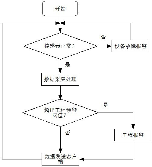
[0035] figure 2 It is a process flow diagram of the comprehensive testing system of the present invention.

[0036] The process flow chart of the comprehensive system of the present invention includes sensor detection, data collection and processing, engineering early warning, and client sending.

[0037] For the sensor detection part, it mainly completes the detection of whether the sensor is good or bad. The sensor is connected to the data acquisition part through a cable. After the connection and installation are completed, it is detected whether there is an overrange or damage. On the basis of ensuring that there are no failure problems, start data collection.

[0038]For the data processing and acquisition part, the resistance strain type acquisition module, the vibrating wire type acquisition module and the piezoelectric acquisition module are mainly installed. The vibrating wire acquisition module mainly processes the vibrating wire sensor connected on the cable, e...

Embodiment 3

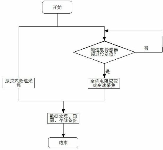
[0044] image 3 It is a flow chart of the data collection and processing part of the present invention.

[0045] In the sensor detection section, each sensor 11....1n detects parameters such as acceleration, settlement, and swing of the building; then enters the data processing section, which collects signals from analog channels and digital channels. In this process, the vibrating wire sensor plays the role of a benchmark. Due to the relatively slow response speed, the long-term monitoring value is stable, and there is no long-term drift, so it is in a low-speed long-term working state. The drift of the building, and monitor the slow sinking and force of the building; the acceleration sensor has been in high-speed working state for a long time, and detects the acceleration of the building in real time, which is used to trigger and close the acquisition of the resistance strain type full bridge signal; the resistance strain type The sensor is in a standby state, and whether i...


PUM


Abstract

The invention belongs to the technical field of sensors, and discloses a multi-sensor comprehensive test system for health monitoring on bridges, towers and high-rise buildings. The comprehensive test system comprises sensors, a data acquisition device, a on-site data monitoring terminal, a network port and a remote client terminal, wherein the sensors include an acceleration sensor, a vibrating wire sensor and a full-bridge resistance strain sensor; and the vibrating wire sensor checks the full-bridge resistance strain sensor and records conditions of long-term slow sinking, force bearing and the like of buildings, and the acceleration sensor triggers and closes the full-bridge resistance strain sensor. With cooperation of the sensors at each part and an acquisition module in the system, the function of comprehensive test is realized, and by the application of the acceleration sensor, the problem that the full-bridge strain sensor is always in a high-speed acquisition state is solved, and thus the comprehensive test system can be widely used for various buildings, and can detailedly record and reflect some geological disaster information in time so as to save financial and material resources for latter health analysis.

Description

technical field [0001] The invention belongs to the technical field of sensors, and more specifically relates to a multi-sensor comprehensive test system suitable for health monitoring of bridges, towers and high-rise buildings. Background technique [0002] Usually, a sensor can only be used to detect one kind of physical quantity, but in many application fields, in order to perfectly and accurately reflect objective things and environments, it is often necessary to measure a large number of physical quantities at the same time. A multifunctional sensor composed of several sensitive elements is a new generation of detection system with small size and multiple functions. It can rely on different physical structures or chemical substances in sensitive elements and their different characterization methods. Use a single sensor system to simultaneously realize the measurement functions of multiple sensors. [0003] The health monitoring of bridges, towers, and high-rise buildin...

Claims


Application Information

Patent Timeline
Patent Type & Authority Applications(China)
IPC IPC(8): H04L29/08G01D21/02
Inventor 胡敬礼王树友李中山
Owner 苏州筑邦测控科技有限公司
Learn More