Asymmetric-incidence-based sample axial position tracking and correcting method and device

An axial position, asymmetrical technology, applied in the direction of measuring devices, optical devices, instruments, etc., can solve the problem of small measurement range, and achieve the effect of fast and accurate adjustment process, high sensitivity and convenient use

Active Publication Date: 2014-01-29
ZHEJIANG UNIV
View PDF4 Cites 0 Cited by
  • Summary
  • Abstract
  • Description
  • Claims
  • Application Information

AI Technical Summary

Problems solved by technology

In 2004, the Chinese invention patent with the patent number ZL200410006359.6 proposed a differential confocal scanning detection method with high spatial resolution. Although this method partially solves the problem of tracking the axial position of microscopic samples, it can better Improve the measurement accuracy of the microscopic system, and effectively avoid the influence of the energy drift of the laser used in the system on the tracking effect, but the measurement range of this method is small, so that it still has great limitations in use

Method used


Image

  • Asymmetric-incidence-based sample axial position tracking and correcting method and device
  • Asymmetric-incidence-based sample axial position tracking and correcting method and device
  • Asymmetric-incidence-based sample axial position tracking and correcting method and device

Examples


Embodiment Construction

[0052] The present invention will be described in detail below in conjunction with the embodiments and accompanying drawings, but the present invention is not limited thereto.

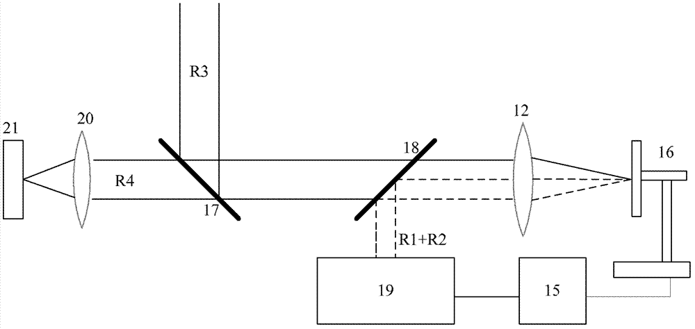
[0053] like figure 1 As shown, a sample axial position tracking correction device based on asymmetric incidence, including: a laser 1, a single-mode fiber 2, a collimator lens 3, a polarizer 4, a polarization converter 5, a 0 / π phase plate 6, Focusing lens 7, spatial filter 8, second collimating lens 9, 3 / 4 shielding plate 10, dichroic prism 11, microscopic objective lens 12, monitoring beam focusing lens 13, photoelectric sensing device 14, computer 15, three-dimensional nano-scanning platform 16.

[0054] Among them, single-mode fiber 2, collimating lens 3, polarizer 4, polarization converter 5, 0 / π phase plate 6, focusing lens 7, spatial filter 8, second collimating lens 9, 3 / 4 shielding plate 10. The dichroic prism 11, the microscopic objective lens 12 and the three-dimensional nano-scanning plat...


PUM


Abstract

The invention discloses an asymmetric-incidence-based sample axial position tracking and correcting method and device. The device comprises a laser, a single-mode optical fiber, a collimating lens, a polarizer, a polarization converter, a 0 / Phi phase plate, a space filtering assembly, a 3 / 4 baffle plate, a beam splitter prism, a microscope objective lens, a monitoring light beam focusing lens, a photoelectric induction device, a computer and a three-dimensional nano scanning platform. The method comprises the following steps of: converting a collimating light beam into a second tangential polarized light, wherein polarization directions of each point on the cross section of the second tangential polarized light are symmetric in respect to two symmetric axes which are mutually vertical at the same time, forming asymmetric incident light beams, focusing the asymmetric incident light beams, and projecting the asymmetric incident light beams onto a sample; meanwhile, collecting light beams reflected by the sample as a monitoring light beam, and monitoring axial position shift of the sample and tracking and correcting the axial position of the sample according to center-of-gravity shift of a focusing spot of the monitoring light beam. The asymmetric-incidence-based sample axial position tracking and correcting method and device disclosed by the invention can be applied to sample axial position real-time monitoring and correcting in a high-accuracy super-resolution microscope system.

Description

technical field [0001] The invention belongs to the field of high-precision and super-resolution microscopy, in particular to a method and device for tracking and correcting the axial position of a sample based on asymmetric incidence. Background technique [0002] In a super-resolution microscope system, the sample to be tested needs to be placed at the focal plane of the microscope objective. However, during the scanning process, due to factors such as thermal drift and stress drift, the sample to be tested will inevitably drift axially over time and deviate from the focal plane, which will seriously affect the imaging accuracy of the microscope system. Especially for microscopic methods that require multiple repeated scans of the same pixel, the impact of this axial drift will be more obvious, because the axial drift may cause multiple repeated scans that are not for the same pixel. Therefore, in order to improve the measurement accuracy of the microscopic system, the a...

Claims


Application Information

Patent Timeline
Patent Type & Authority Patents(China)
IPC IPC(8): G01B11/00G01B9/04
Inventor 匡翠方李帅罗丁刘旭
Owner ZHEJIANG UNIV
Why Eureka
Try Eureka