Eureka AIR delivers breakthrough ideas for toughest innovation challenges, trusted by R&D personnel around the world.

Energy-saving process and energy-saving device for utilization of kiln waste

An energy-saving device and kiln technology, which is applied in the field of ceramic industrial kilns, can solve the problems of high requirements for heat pump technology, physical injury of workers, and the impact of bad brick quality, and achieves the effects of reducing pollution, simple and compact structure, and increasing temperature.

Inactive Publication Date: 2012-07-18
ZIBO HUIJIU AUTOMATION TECH
View PDF4 Cites 4 Cited by
  • Summary
  • Abstract
  • Description
  • Claims
  • Application Information

AI Technical Summary

Problems solved by technology

The device installs a heat pump and pipes above the quenching zone to directly suck the hot air in the kiln and send it to the combustion-supporting section for use. Due to the high temperature of the hot air, the process requirements for the heat pump are very high, and the output hot air brings out nitrogen oxides. , sulfide and other harmful gases and a large amount of dust not only affect the quality of bricks, but also cause serious pollution to the environment and harm the health of the staff

Method used


Image

  • Energy-saving process and energy-saving device for utilization of kiln waste
  • Energy-saving process and energy-saving device for utilization of kiln waste
  • Energy-saving process and energy-saving device for utilization of kiln waste

Examples


Embodiment Construction

[0021] The present invention will be further described below in conjunction with accompanying drawing:

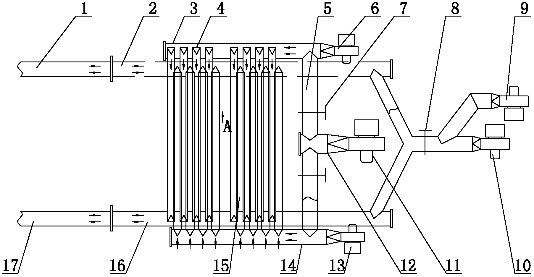
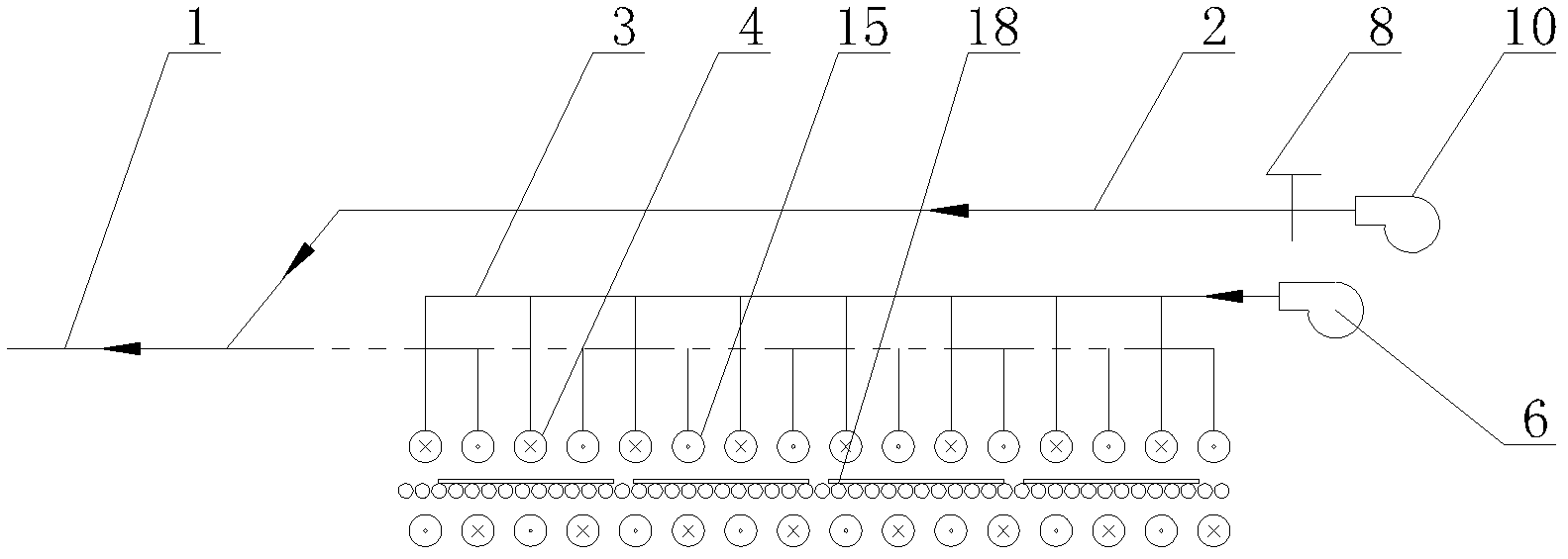
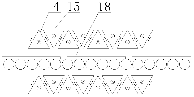
[0022] Such as Figure 1 ~ Figure 3 As shown, the kiln waste heat utilization energy-saving device of the present invention includes a left combustion-supporting pipeline 17 and a right combustion-supporting pipeline 1, and a left air inlet pipeline 14, a left air outlet pipeline 16, and a right air inlet pipeline are arranged in the quenching section of the kiln. 3 and the right air outlet duct 2, and heat collecting pipes are distributed between the air inlet duct and the air outlet duct. Wherein, A is connected to the right air inlet duct 3 to the air inlet of the heat collecting pipe 4, and the air outlet is connected to the left air outlet duct 16, and one end of the right air inlet duct 3 is connected to the right quenching fan 6, and one end of the left air outlet duct 16 is connected to the combustion-supporting fan 10 , and the other end is connected to the left c...


PUM


Abstract

The invention belongs to the technical field of ceramic industrial kilns, and particularly relates to an energy-saving process and an energy-saving device for utilization of kiln waste. The process includes steps: firstly, heat exchange, namely using a quench fan to send cold air into a pipeline of a kiln quench zone, and allowing the cold air passing through the pipeline of the quench zone to exchange heat with the quench zone; and secondly, heat utilization, namely mixing acquired hot air with air conveyed by a combustion fan into a combustion pipeline to raise the temperature of the combustion air to 600-800 DEG C. The energy-saving process and the energy-saving device for utilization of kiln waste have the advantages that the cold air is sent into the pipeline for heat exchange with the quench zone and then recycled, and the cold air only flows in the pipeline with no direct reaction with the interior of the industrial kiln and the surfaces of bricks, so that damage of brick blank is avoided, and the bricks are safer, more reliable and more environment-friendly in use. Moreover, the quench zone can be effectively cooled while the temperature of the combustion zone is raised by raising the temperature and improving the oxygen content of the combustion air.

Description

technical field [0001] The invention relates to an energy-saving process and device for utilizing kiln waste heat, and belongs to the technical field of ceramic industrial kilns. Background technique [0002] The ceramic industrial kiln system generally includes a preheating section, a combustion-supporting section, a rapid cooling section, a slow cooling section and a final cooling section. The average temperature of the adobe during firing in the combustion-supporting section can reach about 1150°C. After reaching the quenching section, the temperature needs to be reduced to about 280°C in a short time, so there is a temperature difference of about 800°C, and the waste heat in this section cannot be fully utilized. , resulting in a waste of resources. The rapid cooling method in the traditional kiln is: open small holes in the pipes, and blow cold air to the surface of the bricks to achieve the purpose of rapid cooling. Due to the effect of high-speed cold air flow in th...

Claims


Application Information

Patent Timeline
Patent Type & Authority Applications(China)
IPC IPC(8): F27D17/00F23L15/00F27D9/00
CPCY02E20/34
Inventor 孙永华陈家仪张惠海郑库张慧张庆花蔡庆庆
Owner ZIBO HUIJIU AUTOMATION TECH
Why Eureka
Eureka Blog
Learn More