
Simply supported-continuous construction method for bridge superstructure

A simple-support variable-continuous construction method technology, which is applied to bridges, bridge construction, erection/assembly of bridges, etc., can solve the problems of large environmental impact, long construction period, and easy damage to bridge decks with cracks in inclined sections, and achieves low cost and overall Good performance and the effect of overcoming cracks in oblique sections

Inactive Publication Date: 2012-07-18
SHANGHAI NO 4 CONSTR
View PDF3 Cites 27 Cited by
  • Summary
  • Abstract
  • Description
  • Claims
  • Application Information

AI Technical Summary

Problems solved by technology

At present, expressway bridges generally adopt the form of fabricated prestressed concrete slab girders and T-beams. This technology has the advantages of short hoisting period, low cost, and convenient factory production. However, simply supported beam structures are prone to oblique section cracks. , the bridge deck is easy to be damaged; for long-span bridges, the balanced cantilever pouring method and the bracket cast-in-place method are adopted. Combining the above advantages, explore a method that not only has a short construction period of simply supported beams, but also can combine the advantages of continuous beams with good integrity, so that the permanence of concrete continuous beam structures can be better guaranteed

Method used


Image

  • Simply supported-continuous construction method for bridge superstructure
  • Simply supported-continuous construction method for bridge superstructure
  • Simply supported-continuous construction method for bridge superstructure

Examples


Embodiment Construction

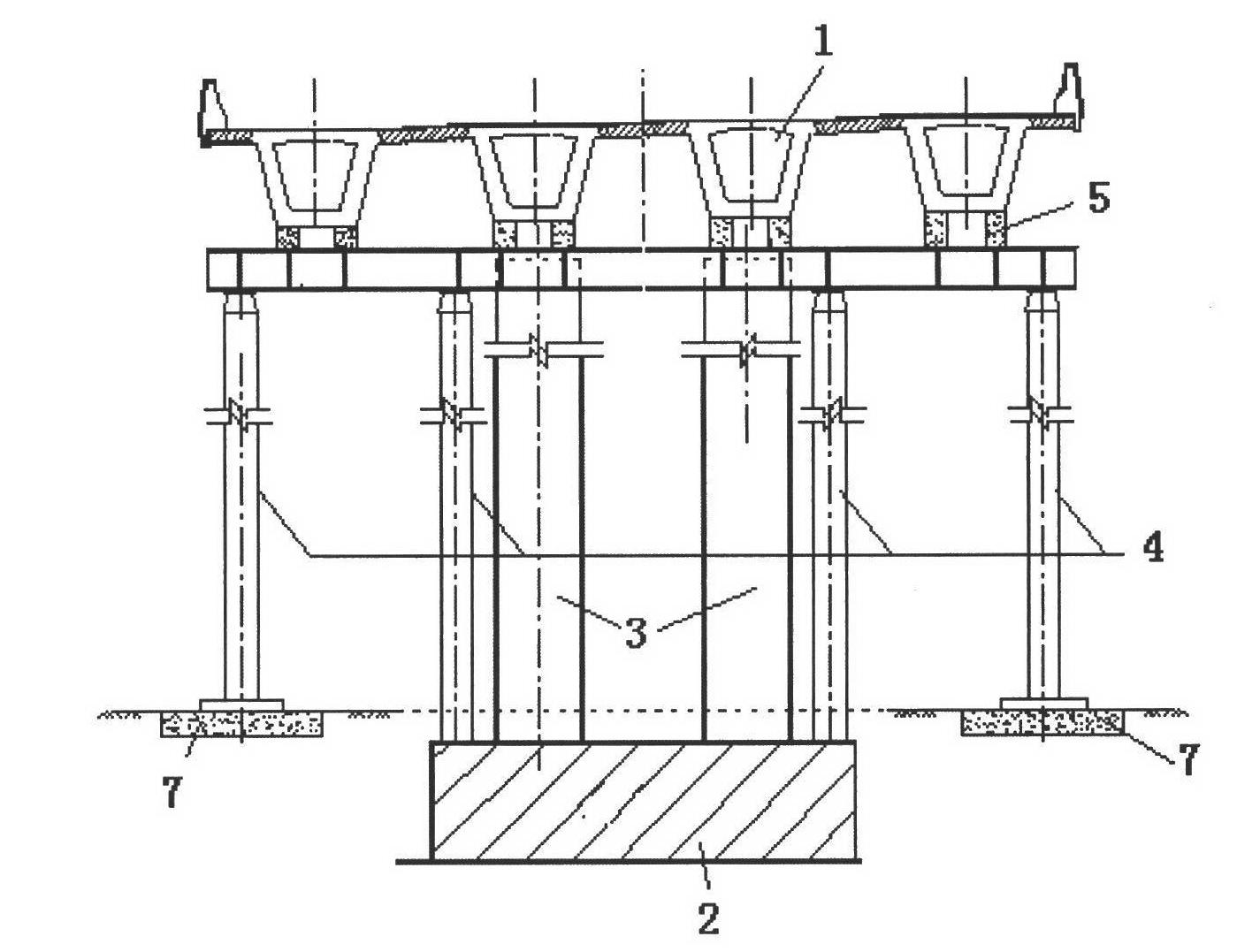
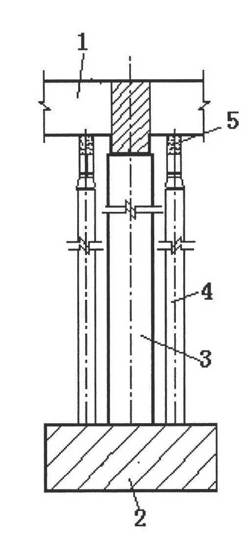
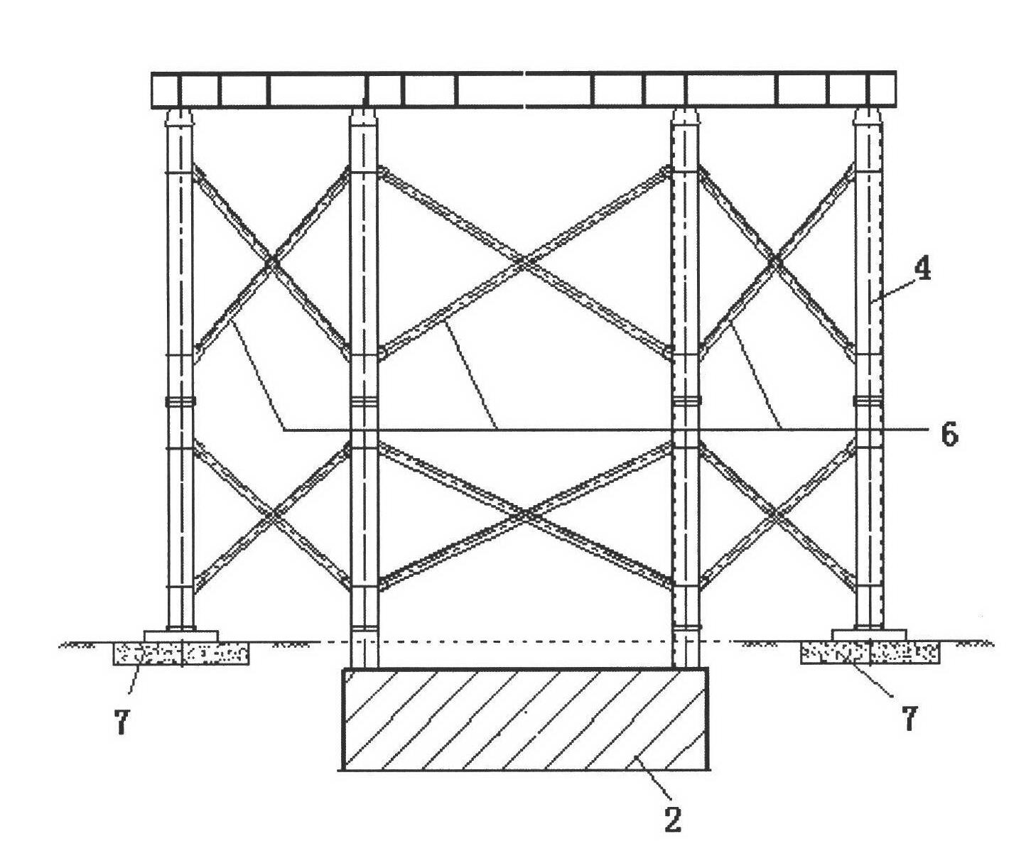
[0023] Such as Figure 1 to Figure 10 As shown, a simple-supported variable continuous construction method for the bridge superstructure, first prefabricated small simply-supported box girders 1 in batches, and then installed temporary steel brackets 4 on both sides of bracket steel pipe columns 3 standing on the cap 2, temporarily A temporary support 5 with adjustable elevation is installed on the top of the steel bracket 4, and the prefabricated simply supported small box girder 1 is hoisted to the temporary support 5 on the temporary steel bracket 4, and then the beam between the simply supported small box girders 1 The transverse prestressed tendons 8 are arranged at the position, and the longitudinal negative moment beams are arranged through the holes reserved on the top surface of the simply supported small box girder 1, and the beam concrete 8 is poured. Prestressed continuous beam system.

[0024] The main construction steps of the bridge superstructure using the sim...


PUM


Abstract

The invention relates to a simply supported-continuous construction method for a bridge superstructure, The method comprises the following steps: firstly, prefabricating standard simply supported small box girders in batch; installing temporary steel brackets at two sides of a bracket steel tube column that is erected on each cushion cap, installing a temporary support with adjustable elevation at the tops of the steel brackets, and lifting the prefabricated simply supported small box girders on the temporary supports arranged on the steel brackets; after that, arranging a transverse prestressed reinforcing steel at the cross beam position between the simply supported small box girders, arranging longitudinal hogging moment bundles through reserved holes arranged at the top surfaces of the simply supported small box girders; pouring concrete into cross beams; and stretching and drawing by use of prestress after the concrete reaches the designed strength to form a two-way prestress continuous beam system. The simply supported-continuous construction method provided by the invention has the characteristics that the simply supported box girder has low manufacturing cost and a simple structure and facilitates industrialized production and lifting work, and a continuous bridge is good in integrity and reasonable in stress, so that the disadvantages that inclined section cracks occur at ends of the simply supported box girders, the bridge surface continuation is liable to damage, and the continuous bridge has high requirement on a foundation and supports and has a complex structure and long construction period can be avoided.

Description

technical field [0001] The invention relates to a construction method of a bridge superstructure, in particular to a construction method of a concrete continuous beam at the top of a bridge. technical background [0002] With the rapid development of expressways in my country, especially for expressways built in the form of elevated within the city limits, the quality requirements for expressway bridge construction have also increased accordingly, and bridge construction technology has attracted more and more attention. At present, expressway bridges generally adopt the form of fabricated prestressed concrete slab girders and T-beams. This technology has the advantages of short hoisting period, low cost, and convenient factory production. However, simply supported beam structures are prone to oblique section cracks. , the bridge deck is easy to be damaged; for long-span bridges, the balanced cantilever pouring method and the bracket cast-in-place method are adopted. , combi...

Claims


Application Information

Patent Timeline
IPC IPC(8): E01D21/00
Inventor 干华铭张寅钱寒军朱伟王东
Owner SHANGHAI NO 4 CONSTR
Learn More