Two-piece ceramic bulb shell and manufacturing method thereof

A manufacturing method and bubble shell technology, applied in electrical components, cold cathode manufacturing, electrode system manufacturing, etc., can solve the problems of affecting performance, deformation of the blank, difficult control, etc., to ensure coaxiality and ensure reliable bonding properties, and the effect of increasing the bonding area

Inactive Publication Date: 2014-04-02
杨潮平
View PDF5 Cites 0 Cited by
  • Summary
  • Abstract
  • Description
  • Claims
  • Application Information

AI Technical Summary

Problems solved by technology

[0004] The butt joint of the two-piece bulb shells by interference fit is achieved by the different shrinkage rates during the sintering process, so it is necessary to form two green bodies with different shrinkage rates and different joint surface structures, and then choose different pre-firing temperatures For pre-firing, the process is more complicated and difficult to control. In addition, the wall thickness of the bulb connected by interference fit needs to be increased, which will also affect the light transmittance of the bulb, and ceramic bulbs may occur in each assembly and sintering step. Component misalignment or defects such as bonding force and air tightness
[0005] The method of butt-joining two-piece bulbs by heating is to form a pair of blanks containing a large amount of adhesive material, and heat the joint to melt the blanks and combine the two components together under external force. Therefore, In the subsequent process, it is difficult to drain a large amount of bonding materials in the green body. For transparent alumina ceramic bulbs, impurities inside are a fatal problem that affects performance. In addition, the green body becomes soft as a whole due to heat conduction. Applying external force, it is easy to deform the green body during the docking process

Method used


Image

  • Two-piece ceramic bulb shell and manufacturing method thereof
  • Two-piece ceramic bulb shell and manufacturing method thereof
  • Two-piece ceramic bulb shell and manufacturing method thereof

Examples


Embodiment 1

[0045] Embodiment 1, making a batch of 150W ellipsoidal two-piece ceramic blister

[0046] 1. According to the requirements, use spray granulated high-purity alumina to form a batch of blister blanks by isostatic pressing.

[0047]2. Configure a batch of slurry, the main component is high-purity alumina powder, add 3% glycerin, 4.5% terpineol, 2% dioctyl phthalate, 1% didecyl phthalate, 2% Epoxy resin, 0.3% polyamide wax, 0.25% hydrogenated castor oil, the viscosity of the test slurry is 32000mPa×S, and the prepared slurry is sealed and stored on a rotating table in a constant temperature box to rotate at a constant speed.

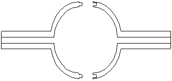
[0048] 3. Put the formed blank capillary down and the cavity joint ring up into the Figure 8 In the jig shown, a thin paste layer is printed on the surface of the bonding ring of the body cavity by using thin film printing technology, and the thickness of the paste layer is about 0.04mm.

[0049] 4. Take half of the green body with printed paste from ...


PUM

PropertyMeasurementUnit
viscosityaaaaaaaaaa
heightaaaaaaaaaa
thicknessaaaaaaaaaa

Abstract

A twinset ceramic blister and a manufacturing method thereof are provided, relating to the technical field of electric light source material preparation. The method comprises the following steps: a. forming a pair of ceramic blister blank of the same shape, the blank being formed by capillaries (1) and a cavity body (2); b. forming one combination ring (3) on a combination surface of the cavity body (2); c. printing a layer of thin slurry for bonding on the surface of the combination ring (3) of each blister blank to be jointed; d. positioning the two blister blanks by using a fixture, so that the slurry on the surface of the combination ring (3) is bonded; and e. drying the jointed blisters, and taking out the blanks bonded together after the slurry is dried; and performing sintering at high temperature and finally forming a twinset ceramic blister. The present invention has the following advantages: the process is simple, the joint manner is reliable, no deformation and dislocation appears on the exterior of the jointed blanks, and the transmittance of the whole blister is not affected after the sintering at high temperature.

Description

technical field [0001] The invention belongs to the technical field of electric light source material preparation, and in particular relates to a two-piece ceramic blister and a manufacturing method thereof. Background technique [0002] At present, two-piece blisters generally adopt the method of interference fit to achieve docking, such as figure 1 As shown, firstly, two green bodies are molded separately, and there is a coupled concave-convex structure at the butt joint of the two green bodies. The two blanks are butted together, and then sintered at high temperature, and the butt joints are combined by interference fit to achieve airtight butt joint. [0003] In recent years, another method of connecting two-piece blisters has emerged, which is to form a ceramic body containing more bonding materials. The two bodies have the same shape. After the joint surface is heated and softened, the two ceramic bodies are combined in the fixture, and then deglue and sintered to re...

Claims


Application Information

Patent Timeline
Patent Type & Authority Patents(China)
IPC IPC(8): H01J1/64C04B35/10C04B35/622
CPCH01J61/302H01J9/266
Inventor 杨潮平
Owner 杨潮平
Why Eureka
Try Eureka