Die clamping device for injection molding machine

A technology of an injection molding machine and a mold clamping device, which is applied in the field of connecting mechanisms, can solve problems such as breakage of connecting parts, and achieve the effect of preventing breakage

Inactive Publication Date: 2012-07-18
MITSUBISHI HEAVY INDS PLASTIC TECH
View PDF5 Cites 6 Cited by
  • Summary
  • Abstract
  • Description
  • Claims
  • Application Information

AI Technical Summary

Problems solved by technology

In this case, as described above, the operating rod 42 of the actuator 41 may be damaged at the connecting portion.

Method used


Image

  • Die clamping device for injection molding machine
  • Die clamping device for injection molding machine
  • Die clamping device for injection molding machine

Examples


no. 1 approach 〕

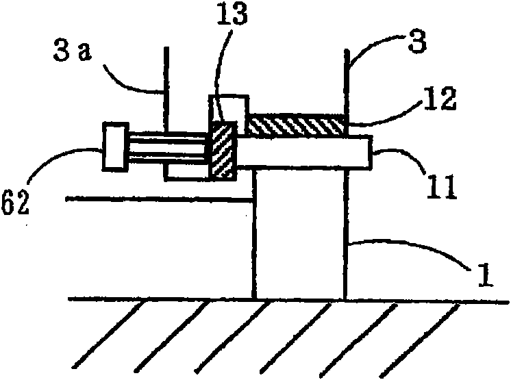
[0074] A first embodiment will be described based on the drawings. figure 1 is a side view of the injection molding device according to the present invention, figure 2 Yes figure 1 A-A sectional view of, image 3 Yes figure 2 Enlarged view of Part B, Figure 4 yes means figure 1 The top view of the mold plate and the mold plate opening and closing mechanism of the injection molding device (the double dotted line indicates the movable mold plate when the mold is opened), Figure 5 Yes Figure 4 The detailed drawing of the connecting part C of the mold plate and the mold plate opening and closing mechanism, Image 6 yes means Figure 4 The tilted top view of the movable die plate when one side of the side guide plate is worn, Figure 7 Yes Image 6 Enlarged view of part E of (one of), Figure 8 Yes Image 6 Enlarged view of Part E of (Part 2), Figure 9 yes means Figure 4 An enlarged view of the position of the front end of the hydraulic piston rod at the conn...

no. 2 approach 〕

[0094] This embodiment differs from the first embodiment in that the hydraulic cylinder is connected to the fixed die plate side. Other than that, the structure is the same, and the functions are also completely the same, so the description of the common parts will be omitted.

[0095] A second embodiment will be described based on the drawings. Figure 13 is a side view of the injection molding apparatus according to the second embodiment, Figure 14 Yes Figure 13 Enlarged view of part G of Figure 15 Yes Figure 14 The H-H sectional view, Figure 22 Yes Figure 15 Enlarged view of part M of .

[0096] In the drawing, a hydraulic cylinder 51 for opening and closing the movable mold plate is provided with a support ring 51a of the pin joint connection mechanism 20, and a pair of pin receiving parts 22 mounted by fastening bolts 24 are fixedly provided on the support ring 51a. One end of the connecting pin 23 is inserted into the pin receiving portion 22 , and the other ...


PUM


Abstract

The present invention prevents breakage of a moving actuator of a movable die board relative to a stationary die board in a die clamping device for an injection molding machine. A die clamping device is provided with a movable die board moving means for bringing a movable die board (3) close to/away from a stationary die board (2) in the horizontal direction, the movable die board moving means comprising: an actuator (41) for moving/driving the movable die board (3); a clevis pin for connecting a tip end of an actuation rod (42) of the actuator (41) with the movable die board (3); a clevis pin fixing member for supporting the central shaft of the clevis pin in the direction perpendicular to the moving direction of the movable die board and fixing the clevis pin to the movable die board; and a clevis pin connection member for connecting the actuator and the clevis pin. The clevis pin connection member has a support structure rotatable by the clevis pin and is supported by the movable die board via the clevis pin fixing member, and the clevis pin, the clevis pin connection member, and the tip end portion of the actuator are arranged in series.

Description

technical field [0001] The invention relates to a mold plate opening and closing device of an injection molding machine, in particular to a connection mechanism between an action end of an actuator capable of driving a movable mold plate forward and backward and a movable mold plate. Background technique [0002] Conventionally, in the mold plate opening and closing mechanism of the injection molding machine, as described in Patent Document 1 and Patent Document 2, hydraulic or electric actuators are directly fixed to the movable mold plate and the fixed mold plate. or as Figure 16 , Figure 17 As shown, the connection between the movable mold plate and the actuator consists of a pressing member 61 mounted on the movable mold plate 3 and an actuator 41 having a groove portion that engages with the pressing member 61 in an engaging manner. 42, the pressing member 61 and the front end 45 of the operating rod 42 of the actuator 41 are connected with a slight gap S1, S2. [0...

Claims


Application Information

Patent Timeline
Patent Type & Authority Applications(China)
IPC IPC(8): B29C45/64
CPCB29C45/1761B29C45/64B29C45/03
Inventor 藤田三郎
Owner MITSUBISHI HEAVY INDS PLASTIC TECH
Why Eureka
Try Eureka