Crankshaft turning tool

A crankshaft and tooling technology, which is applied in the field of crankshaft turning tooling, can solve the problems of large number of eccentric shafts, large clamping diameter, and low work efficiency, so as to increase the amount of back cutting, increase the clamping force, and reduce the workload Effect

Inactive Publication Date: 2014-04-02
NORTHWESTERN POLYTECHNICAL UNIV
View PDF5 Cites 0 Cited by
  • Summary
  • Abstract
  • Description
  • Claims
  • Application Information

AI Technical Summary

Problems solved by technology

[0004] In order to solve the problems in the prior art that the clamping force is small, it is not easy to balance the weight, the work efficiency is low, and it is not suitable for crankshafts with large clamping diameters, large numbers of eccentric shafts, and large eccentric distances, etc., the present invention proposes a crankshaft Turning tooling

Method used


Image

  • Crankshaft turning tool
  • Crankshaft turning tool
  • Crankshaft turning tool

Examples


Embodiment Construction

[0016] The present invention is described below in conjunction with specific embodiments.

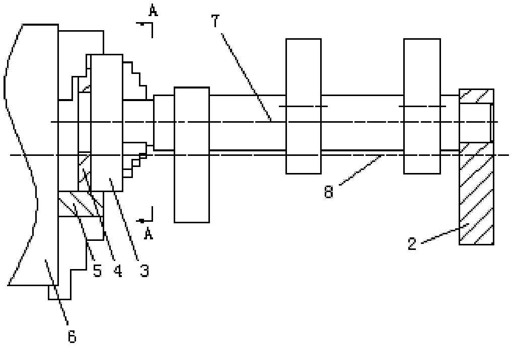
[0017] Refer to attached figure 1 , The crankshaft turning tooling in this embodiment includes a three-jaw self-centering chuck 3, an indexing plate 4, a four-jaw single-action chuck 6, a front eccentric pad 5, a rear eccentric top block 2 and a counterweight 1.

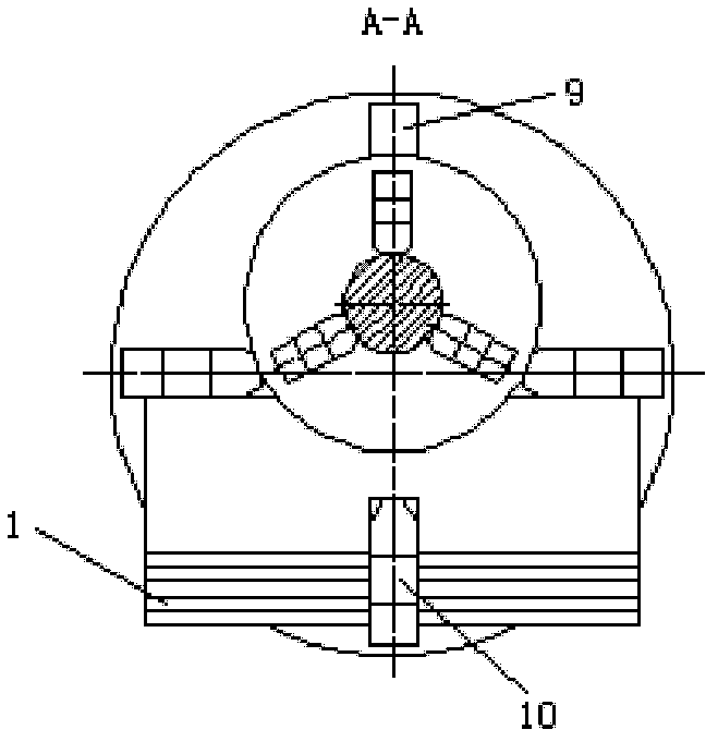
[0018] The four-jaw single-action chuck is fixedly installed on the rotating shaft end of the horizontal lathe. The front eccentric pad 5 and the three-jaw self-centering chuck 3 are clamped on the four-jaw single-action chuck, wherein the front eccentric pad 5 is fixed between the four-jaw single-action chuck 6 and the three-jaw self-centering chuck 3 room, refer to the attached image 3 , there is a groove at the lower part of the front eccentric block Arc groove on the upper part The front eccentric pad is clamped on the lower jaw 10 of the four-jaw single-action chuck through the lower groove, and the arc groove on t...


PUM


Abstract

The invention provides a crankshaft turning tool, which comprises a three-jaw self-centering chuck, an indexing disc, a four-jaw independent chuck, a front eccentric cushion block, a rear eccentric ejector block and a balancing weight. The front eccentric cushion block and the three-jaw self-centering chuck are clamped on the four-jaw independent chuck, a plurality of radial positioning grooves are uniformly arranged on the indexing disc and match with a clamping jaw at the upper end of the four-jaw independent chuck, the three-jaw self-centering chuck is positioned and naturally indexed by means of selecting different radial positioning grooves to clamp the clamping jaw at the upper end of the four-jaw independent chuck, a workpiece mounting hole matching with an outer circle of a crankshaft is arranged on the rear eccentric ejector block, two jackscrew holes are disposed on a side wall of the workpiece mounting hole, a center hole is further arranged on the rear eccentric ejector block, and the distance from the axis of the center hole to the axis of the workpiece mounting hole is equal to the eccentricity of the crankshaft. Natural indexing is realized by the aid of the indexing disc, workload of a scribing working procedure is reduced, a working procedure for machining center holes at two ends of a machined workpiece of a boring machine is omitted, and production cost is reduced.

Description

technical field [0001] The invention relates to the technical field of mechanical processing, in particular to a crankshaft turning tooling. Background technique [0002] At present, when a horizontal lathe is used to process a crankshaft, a chicken heart clip is often used. During processing, two tops are used to press against the corresponding center hole of the workpiece. The lathe uses a dial fixed on the chuck to move the chicken heart clip to rotate, thereby driving the entire workpiece. Make a rotary motion. However, when the crankshaft has the characteristics of large volume, irregular shape, center of gravity deviating from the main axis of the workpiece, large eccentric circle diameter, large eccentric distance, and multiple eccentric outer diameters, the existing processing method will have low clamping force. , not easy to counterweight, low work efficiency and other shortcomings, so the existing crankshaft processing method is not suitable for crankshafts with ...

Claims


Application Information

Patent Timeline
Patent Type & Authority Patents(China)
IPC IPC(8): B23Q3/00
Inventor 刘红军周洲王正平童小燕姚磊江
Owner NORTHWESTERN POLYTECHNICAL UNIV
Why Eureka
Try Eureka