Pneumatic horizontal booster pump spraying filling machine

A pneumatic pressurization and booster pump technology, applied in spraying devices, liquid spraying devices, etc., can solve the problems of unsatisfactory spraying and pouring quality and effect, affecting the mixed use of raw materials, high heating temperature overshoot, etc., to achieve convenient and fast maintenance maintenance, saving manpower, and reducing the frequency of replacement

Active Publication Date: 2014-10-29
京华派克邯郸机械科技有限公司
View PDF5 Cites 0 Cited by
  • Summary
  • Abstract
  • Description
  • Claims
  • Application Information

AI Technical Summary

Problems solved by technology

However, the booster pumps of various existing equipment are mostly vertical or hydraulic, which generally have the disadvantages of large volume and heavy weight, especially for hydraulic equipment. In addition, the insulation tube group connected to the equipment, It makes it more difficult to move and transport the equipment; while the vertical booster pump has poor sealing performance and uneven force, it is easy to cause leakage of material and liquid, which makes operation and equipment maintenance more difficult; in terms of raw material heating control , the control is not accurate enough, and the overshoot value of heating temperature is too high, which is a common phenomenon in this type of equipment. The high overshoot value affects the mixed use of raw materials to a certain extent, resulting in unsatisfactory quality and effect of spraying and pouring

Method used


Image

  • Pneumatic horizontal booster pump spraying filling machine
  • Pneumatic horizontal booster pump spraying filling machine
  • Pneumatic horizontal booster pump spraying filling machine

Examples


Embodiment Construction

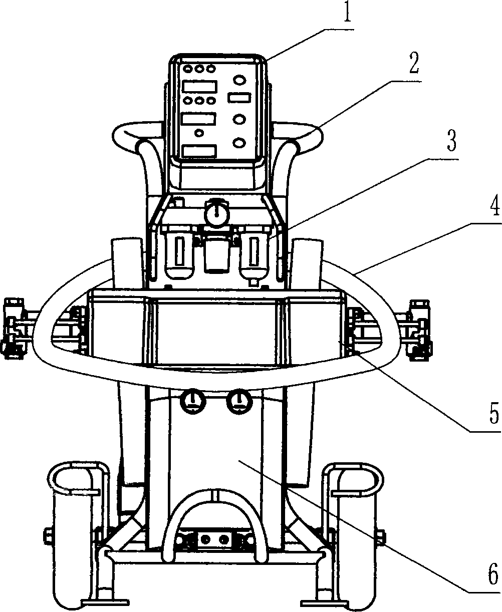
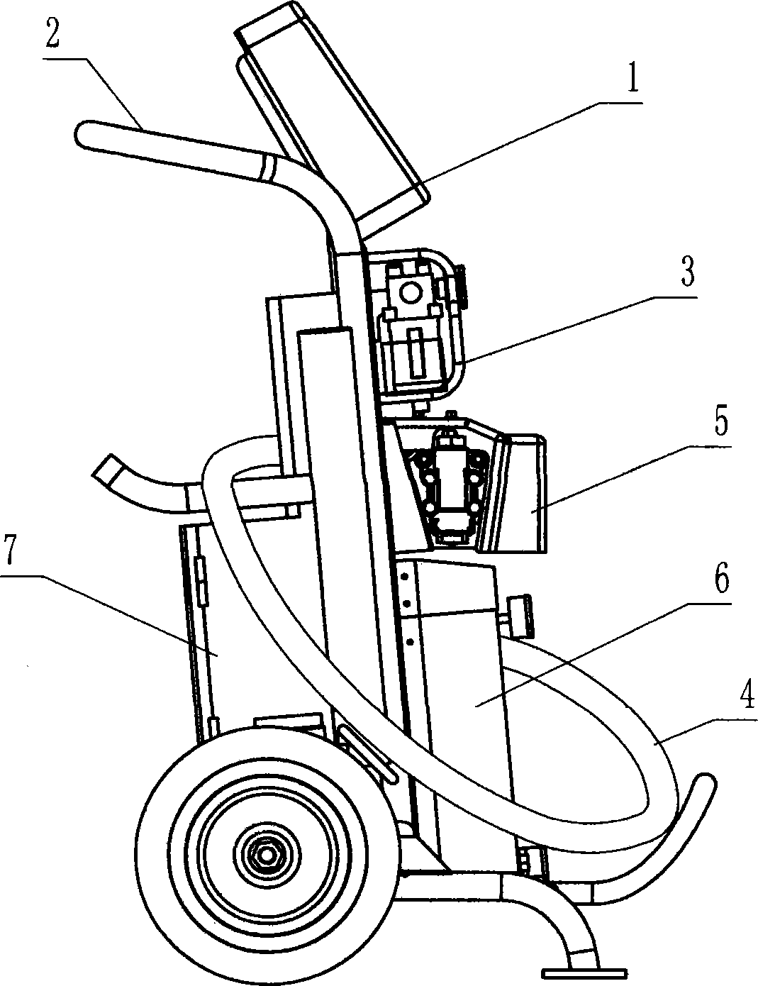
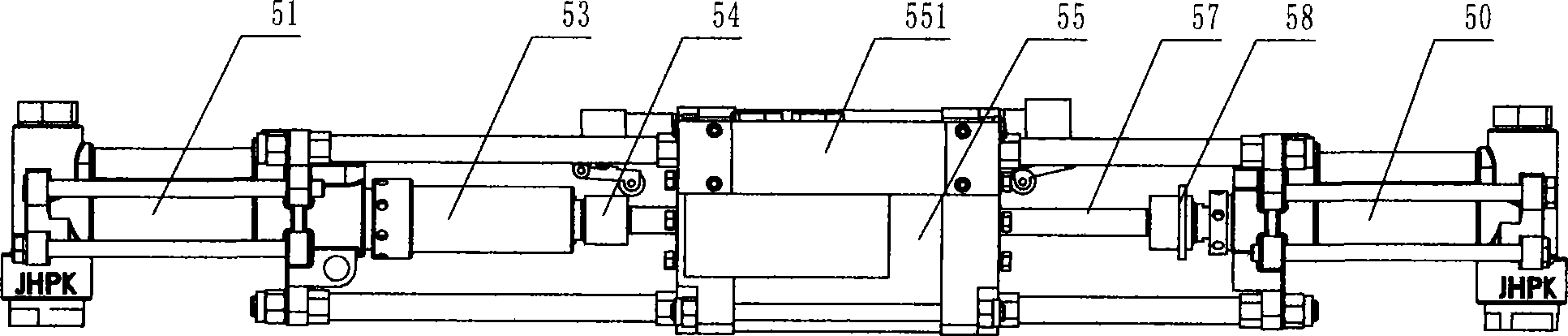
[0023] The present invention will be further described below with reference to the accompanying drawings and embodiments. Examples: refer to the accompanying drawings, a pneumatic flat-mounted booster pump spraying and filling machine, with a frame 2 with two wheels and handles, and an operating panel on the frame 1. Pneumatic triplet connected to the power source 3, heater for heating and insulating the raw materials 6, control box 7, pneumatic booster pump 5, heat preservation pipe 4, the operation panel is controlled and signaled with the control box and the pneumatic triplet The control box is connected to the heater control; the pneumatic booster pump is horizontally arranged on the frame, and a cylinder 55 is arranged in the middle of the pneumatic booster pump. The cylinder is pneumatically connected to the pneumatic triplet through the valve body control assembly 551; The piston in the middle is provided with two left and right cylinder piston rods 56, 57. The two piston...


PUM


Abstract

The invention discloses a spraying and filling machine for a pneumatic horizontal booster pump. The spraying and injecting machine is provided with a rack, an operation panel, a pneumatic triplet, a heater, a control box, a pneumatic booster pump and a heat preservation pipe, wherein the pneumatic booster pump is arranged on the rack horizontally, an air cylinder is arranged in the middle of the pneumatic booster pump, two piston rods are respectively in power connection with plunger rods of black and white material plunger pumps, a lubrication cylinder is arranged in the black material plunger pump, a wrapping layer is arranged on the heat preservation pipe, a heating wire, a black material pipe, a white material pipe and an air pipe are arranged in the wrapping layer, a temperature sensor is arranged in the black material pipe, and a shafting shaft connecting piece is composed of a shaft connecting piece, a shaft end boss, a positioning sleeve and a retainer ring. The spraying and filling machine for the pneumatic horizontal booster pump applies to in-time mixing and in-time spraying and filling, and the spraying and filling of black and white liquid materials which need heating, and is compact in structural design, light in use, simple in operation, simple and convenient to maintain, clean and environment-friendly, good in spraying filling effect and high in efficiency, is unlikely to mix or leak in material and is unlikely to crystallize in black material.

Description

Technical field [0001] The invention belongs to the technical field of tools for spraying and pouring of liquid materials, in particular to a multi-component spraying and pouring machine for instant mixing of multi-component materials with special ratio, pressure and temperature requirements before mixing, The spray and infusion machine is widely used in the application fields of polyurethane, polyurea, fireproof coatings and other materials. technical background [0002] At present, in industries such as heat preservation, anti-corrosion, and waterproofing, multi-component spray and infusion equipment for instant mixing of multi-component materials and instant spray and infusion has been widely used. There are many types and different structures. It is an important spray Perfusion tool. However, most of the existing booster pumps of various equipment are vertical or hydraulic, which generally have the disadvantages of large volume and heavy weight, especially hydraulic equipmen...

Claims


Application Information

Patent Timeline
Patent Type & Authority Patents(China)
IPC IPC(8): B05B7/00B05B15/00
Inventor 果枫松杨文波沈长根
Owner 京华派克邯郸机械科技有限公司
Why Eureka
Try Eureka