
Spray-type evaporative cooling and circulating system of heating device

An evaporative cooling and heating device technology, applied in cooling/ventilation/heating renovation, instruments, electrical digital data processing, etc., can solve the problems of cooling efficiency to be improved, expensive cooling medium, high medium cost, low noise, structure Simple, efficient cooling effect

Inactive Publication Date: 2012-07-11
INST OF ELECTRICAL ENG CHINESE ACAD OF SCI
View PDF4 Cites 54 Cited by
  • Summary
  • Abstract
  • Description
  • Claims
  • Application Information

AI Technical Summary

Problems solved by technology

[0010] Chinese patent 200910243551.X proposes a "surface-mounted evaporative cooling device for supercomputers". This device uses heating elements to be attached to the cooling box, conducts heat to the outer surface of the cooling box, and then conducts heat with the cooling medium in the cooling box. In exchange, this method has the following disadvantages: a. The cooling efficiency needs to be improved
b. The liquid box needs to be processed with high technology, and the structure is complex
[0011] In the past, evaporative cooling was mainly used on power devices and large motors, and cooling methods such as immersion were used. With the banning of the cooling medium Freon 113 (environmental protection requirements), the current alternative cooling medium is expensive (about 400 yuan / kg), If the amount of cooling medium is large, the medium cost is relatively high

Method used


Image

  • Spray-type evaporative cooling and circulating system of heating device
  • Spray-type evaporative cooling and circulating system of heating device
  • Spray-type evaporative cooling and circulating system of heating device

Examples


Embodiment Construction

[0024] The present invention will be further described below in conjunction with the accompanying drawings and specific embodiments.

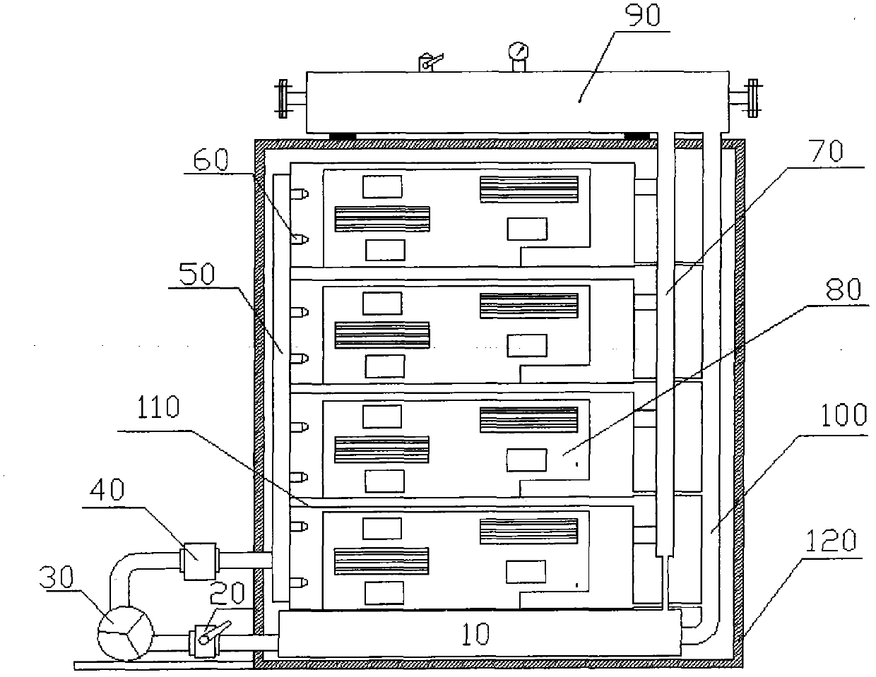
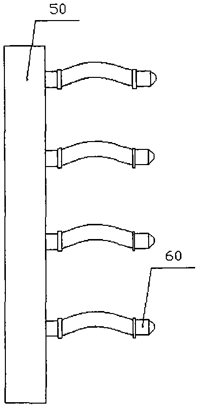
[0025] The concrete implementation method of the present invention is as figure 1 shown. The present invention includes a liquid storage tank 10, a control valve 20, a circulating pump 30, a filter 40, a liquid distributor 50, a nozzle 60, a gas collecting pipe 70, a condenser 90, a liquid return pipe 100, an element sealing box 110 and a heating device cabinet Body 120. The heating device cabinet 120 includes N element sealing boxes 110, N≥1; the element sealing box 110 includes N heating units 80, N≥1; the control valve 20 is arranged between the liquid storage tank 10 and the circulation pump 30 Between, used to adjust the circulating pump flow. The filter 40 is arranged at the front end of the liquid distributor 50 , and the liquid distributor 50 is placed anywhere inside the heating device cabinet 120 ; multiple nozzles 60 are installed...


PUM


Abstract

The invention provides a spray-type evaporative cooling and circulating system of a heating device. A plurality of element seal boxes (110) are arranged in a heating device cabinet (120), a control valve (20) is arranged between a liquid storage tank (10) and a circulating pump (30), a filter (40) is arranged on the front end of a liquid distributor (50), the liquid distributor (50) is arrange on any position in the heating device cabinet (120), a plurality of nozzles (60) are installed on the liquid distributor (50), and one end of a gas collecting tube (70) is connected with the element seal boxes (110). After an evaporative cooling medium atomized by the nozzles (60) exchanges heat with a heating unit (80), the liquid part in the evaporative cooling medium returns to the liquid storage tank (10) through a liquid return tube (100), the evaporated evaporative cooling medium rises to a condenser (90) through the gas collecting tube (70), is condensed by the condenser (90) to become liquid, and returns to the liquid storage tank (10) through the liquid return tube (100).

Description

technical field [0001] The invention relates to a cooling technology, in particular to a spray evaporative cooling technology. Background technique [0002] The thermal problem under the condition of multi-field coupling of electric field, magnetic field and flow field in electromechanical conversion and electric energy conversion has always been a complex frontier topic. The calculation of heat and heat transfer control are the constraints that restrict the capacity improvement and A key issue for performance improvement. [0003] At the same time, the development trend of electronic equipment (including: supercomputers, converters, frequency converters, etc.) is large capacity miniaturization and high power density. This trend will inevitably lead to more and more serious heating of electronic equipment. Electronics with high power density At the same time, the equipment has become a heat generating device with a very prominent thermal problem, and the lack of effective c...

Claims


Application Information

Patent Timeline
Patent Type & Authority Applications(China)
IPC IPC(8): H05K7/20G06F1/20
Inventor 阮琳李振国顾国彪熊斌陈彪董海虹刘斐辉张鹏
Owner INST OF ELECTRICAL ENG CHINESE ACAD OF SCI
Learn More