
Dual-filter duplexer

A duplexer and double filter technology, applied in the electronic field, can solve problems such as difficult high-order harmonic suppression, low harmonic suppression, and large radiation interference, and achieve improved isolation, high harmonic suppression, and strong anti-interference ability Effect

Inactive Publication Date: 2012-07-11
DFINE TECH
View PDF0 Cites 2 Cited by
  • Summary
  • Abstract
  • Description
  • Claims
  • Application Information

AI Technical Summary

Problems solved by technology

[0008] This invention aims to solve the problem of large radiation interference between the two high and low filters in the traditional duplexer, large insertion loss, low harmonic suppression, and difficulty in detecting high-order harmonics. Carry out technical problems such as suppression to provide a double-filter duplexer with the advantages of avoiding radiation interference between filters, small insertion loss, and suppressing 200 times or even higher harmonics of the working frequency.

Method used


Image

  • Dual-filter duplexer
  • Dual-filter duplexer

Examples


Embodiment Construction

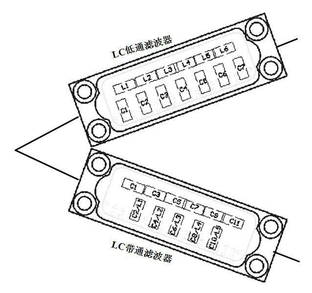
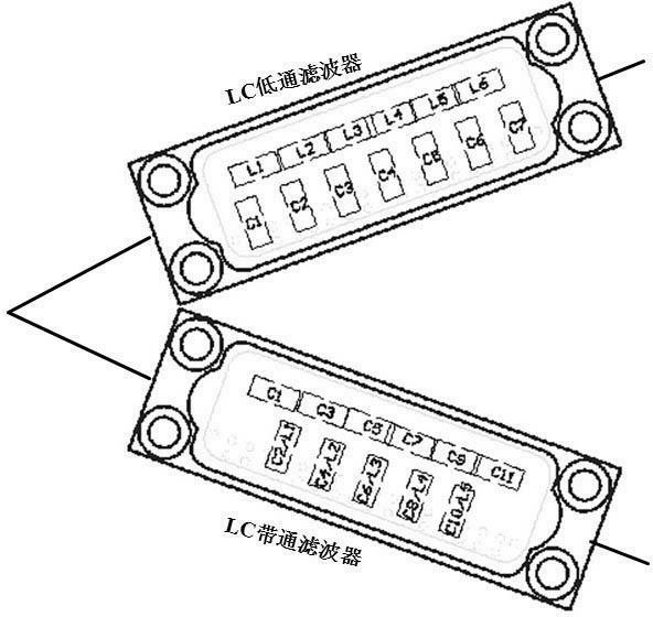
[0019] The detailed structure of the present invention, application principle, function and effect, refer to the appended figure 1 , which will be described through the following embodiments.

[0020] The invention is composed of an LC low-pass filter and an LC band-pass filter. The input terminals of the LC low-pass filter and the LC band-pass filter are connected and connected with an external signal source, and the output terminals of the two are respectively output to the outside. The low-pass LC filter passes the signal of 5MHz to 10MHz with low loss.

[0021] Low-pass LC filter: pass the signal of 5MHz~10MHz with low loss, and the suppression (isolation) of harmonics, especially 950MHz~1600MHz, is as high as 80dB or more.

[0022] Band-pass LC filter: Pass the signal of 950MHz~1600MHz with low loss, and have a high degree of suppression (isolation) for the signal and harmonics of 5MHz~10MHz, as high as 80dB or more.


PUM


Abstract

The invention provides a dual-filter duplexer, relates to the field of electronic technology, and aims to solve the technical problems of a traditional LC duplexer that large radiated interference, large insertion loss and low harmonic suppression exist between two high-and-low-pass filters and difficulty exists in suppressing higher harmonics. The dual-filter duplexer consists of an LC low-pass filter and an LC band-pass filter, wherein the LC low-pass filter is connected with the input terminal of the LC band-pass filter and also connected with an external signal source; and the output terminals of the two filters respectively output outwards.

Description

technical field [0001] The invention relates to the field of electronic technology, in particular to a double-filter duplexer applied to microwave communication, satellite communication, electronic equipment and the like. Background technique [0002] The duplexer is an important component in the communication system. High isolation is an important guarantee for signals of different frequencies to share the same port without interfering with each other. The usual duplexer places the components directly on the same PCB, and the signals will radiate and interfere with each other. [0003] When the working frequency of the low frequency band is within the range of 5-10MHz, the high-frequency band works at 950MHz-1600MHz, and the high-frequency band works at 100 times or more of the low-frequency band, usually the tenth harmonic of the filter is difficult to deal with and is common. The following deficiencies: [0004] 1) It is difficult to avoid the mutual radiation interfer...

Claims


Application Information

Patent Timeline
IPC IPC(8): H03H7/01
Inventor 王家彬姚华
Owner DFINE TECH
Learn More