Pressure-sensitive type fiber sensing device for perimeter security protection
An optical fiber sensing and optical fiber technology, which is applied in the direction of using optical devices to transmit sensing components, optical device exploration, and pressure-dependent alarms, etc. and other problems, to achieve the effect of high practical value, flexible use, and improved test sensitivity
- Summary
- Abstract
- Description
- Claims
- Application Information
AI Technical Summary
Problems solved by technology
Method used
Image
Examples
Embodiment 1
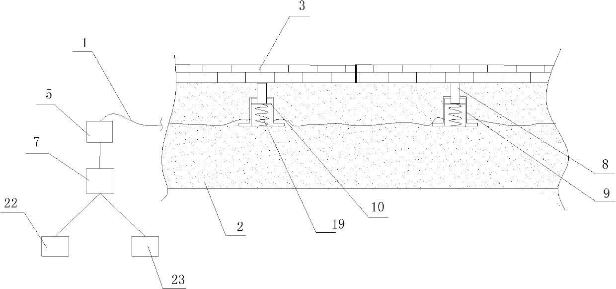
[0040] Such as figure 1 , figure 2 with image 3 A pressure-sensitive optical fiber sensing device for perimeter security is shown, including at least one optical fiber bending sensitive element arranged under the pavement slab 3 and embedded in the soil layer 2, and all optical fiber bending sensitive elements contain signal optical fibers 33 , and when there are two or more optical fiber bending sensitive elements, the signal optical fiber 33 in the optical fiber bending sensitive element is connected in series through the optical cable 1, at least one end of the optical cable 1 is connected with a test unit 5, and the test unit 5 is connected with Processing unit 7, described processing unit 7 is connected with alarm 22 and camera 23; Described optical fiber bending sensitive element comprises a guide rod 8 and the housing 9 that slides with guide rod 8, and guide rod 8 one end is connected with road slab 3 The lower bottom surface is a contact fit, and the other end of ...
Embodiment 2
[0050] Such as Figure 4 , Figure 5 As shown, in this embodiment, the difference from Embodiment 1 is that the curved support is a spring 38, and the deformation teeth 4-1 on the A side and the deformation teeth 4-2 on the B side are correspondingly arranged adjacent to each other in the spring 38. Between the two coils of spring wires, the deformation teeth 4-1 on the A side and the deformation teeth 4-2 on the B side are alternately arranged. In this embodiment, the structures, connections and working principles of other parts are the same as those in Embodiment 1.
Embodiment 3
[0052] Such as Image 6 , Figure 7 As shown, in this embodiment, the difference from Embodiment 1 is that the curved bracket is a bellows 40, and the deformation teeth 4-1 on the A side and the deformation teeth 4-2 on the B side are correspondingly arranged on the pipe wall of the bellows 40 On the two opposite side surfaces of the inner recess on 41, the A-side deformed teeth 4-1 and the B-side deformed teeth 4-2 are alternately arranged. In this embodiment, the structures, connections and working principles of other parts are the same as those in Embodiment 1.
PUM
 Abstract
Description
Claims
Application Information
 - R&D
- Intellectual Property
- Life Sciences
- Materials
- Tech Scout
- Unparalleled Data Quality
- Higher Quality Content
- 60% Fewer Hallucinations
Browse by: Latest US Patents, China's latest patents, Technical Efficacy Thesaurus, Application Domain, Technology Topic, Popular Technical Reports.
© 2025 PatSnap. All rights reserved.Legal|Privacy policy|Modern Slavery Act Transparency Statement|Sitemap|About US| Contact US: help@patsnap.com


