
Straight line segment approximation node-based numerical control system contour error control method

A contour error, numerical control system technology, applied in the field of error compensation control, can solve the problems of large calculation error, unstable calculation, difficult to accurately predict the degree of lag, etc., and achieve the effects of good real-time performance, high calculation accuracy and simple calculation.

Inactive Publication Date: 2012-07-11
SHANDONG UNIV OF TECH
View PDF4 Cites 14 Cited by
  • Summary
  • Abstract
  • Description
  • Claims
  • Application Information

AI Technical Summary

Problems solved by technology

The above method is relatively simple, but due to inertia, friction and other reasons, there is a hysteresis phenomenon in the movement of each feed axis of the actual CNC machine tool, and the degree of hysteresis is difficult to accurately predict. Therefore, the disadvantage of the above contour error calculation method is that the calculation is unstable. When the lag exceeds one sampling period, the calculation error is large, and the calculation error is not easy to control
[0004] In the paper "A multi-axis contour error controller for free form curves" published in the academic journal "JSME International Journal" (2004, 47(1): P144-149), Myung-Hoon LEE et al., except for the X axis, Y In addition to designing PID position controllers for axis and Z axis respectively, for the contour error obtained by approximate calculation, another set of PID contour error controller is designed. The calculation is more cumbersome, which limits the real-time performance of the CNC system.

Method used


Image

  • Straight line segment approximation node-based numerical control system contour error control method
  • Straight line segment approximation node-based numerical control system contour error control method
  • Straight line segment approximation node-based numerical control system contour error control method

Examples


Embodiment Construction

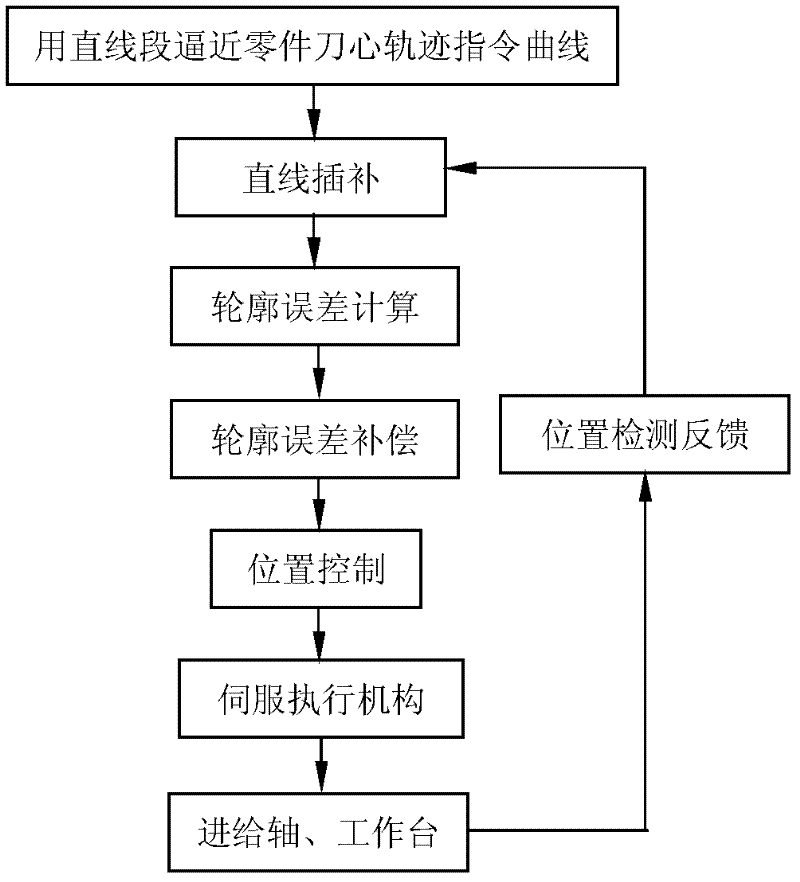
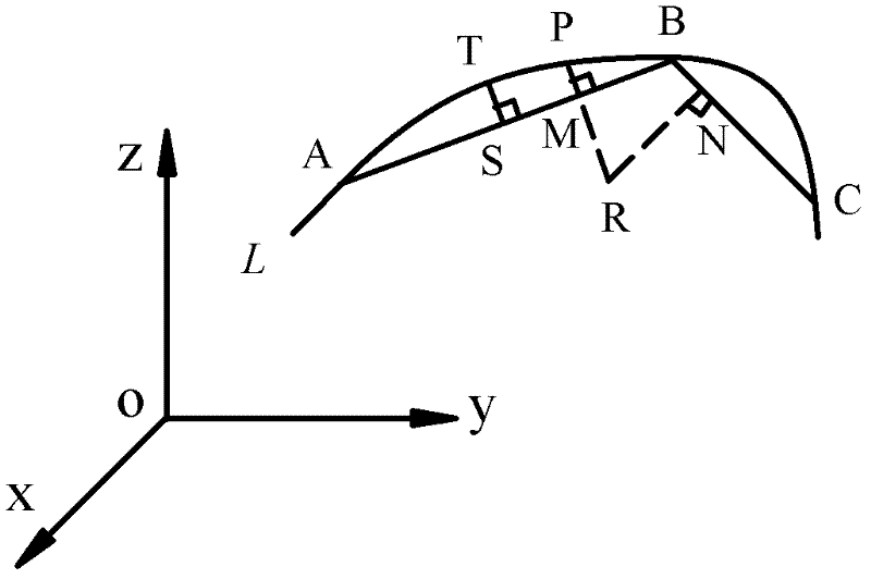
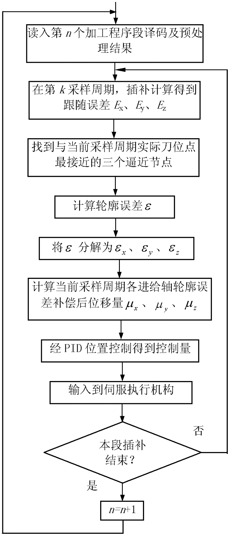
[0019] Combine below Figure 1~3 The present invention is described in further detail:

[0020] Step 1), after using the straight line segment to approach the command curve of the tool center trajectory of the machined part according to the equal error method, in each sampling period of the NC linear interpolation machining of the part, calculate the actual value of the current sampling period according to the position detection of the feed axis and the worktable. Tool position point coordinates, according to the actual tool position point and the approximation node when approaching the command curve of the tool center path with a straight line segment, calculate the shortest distance from the current actual tool position point to the command curve of the tool center path, that is, the contour error. Specific as figure 2 As shown, it is assumed that straight line segments AB, BC, etc. are used to approach the tool center trajectory command curve L of the part according to th...


PUM


Abstract

The invention provides a straight line segment approximation node-based numerical control system contour error control method, which comprises the following steps of: (1) calculating contour error; and (2) compensating the contour error; the contour error control method is characterized in that: in the step (1), after a cutter core trail instruction curve of a machining part is approximated by using a straight line segment according to an equal error method, and the shortest distance, namely contour error, is calculated from a current actual cutter location point to the cutter core trial instruction curve in each sampling period of numerical control straight line interpolation machining of the part according to the current actual cutter location point and an approximation node during approximation of the cutter core trial instruction curve by using the straight line segment; and in the (2), the calculated contour error and following error of the current sampling period are superposed,a superposition result is transmitted to a numerical control system PID (Proportion Integration Differentiation) position controller to calculate position control and is output to a servo execution mechanism to realize contour error compensation. The contour error control method has the advantages of stable contour error calculation method, high calculation accuracy, simple calculation of contourerror compensation method and high real-time property.

Description

technical field [0001] The invention relates to an error compensation control method, in particular to a contour error compensation control method of a numerical control system based on a straight line segment approaching a node. Background technique [0002] In the manufacturing industry, the contour shape of many parts is complex, and the contour curve includes analytical curve, segmented curve, list curve, etc. For the processing of these complex parts, the complex tool center trajectory command curve is often approached by a straight line segment, and then processed by a multi-axis CNC machine tool. For multi-axis CNC machine tools, contour accuracy is the most important factor in determining its machining accuracy. The improvement of contour accuracy involves whether the dynamic characteristics of each feed axis of the machine tool match, and is a combination of the single-axis position accuracy of each coordinate axis and the multi-axis linkage accuracy. Since the se...

Claims


Application Information

Patent Timeline
Patent Type & Authority Applications(China)
IPC IPC(8): G05B19/19
Inventor 赵国勇赵玉刚张丽丽申永
Owner SHANDONG UNIV OF TECH
Learn More