Camera module

A technology of camera module and lens module, which is applied in image communication, television, camera, etc.

Inactive Publication Date: 2012-07-11
SAMSUNG ELECTRO MECHANICS CO LTD
View PDF6 Cites 5 Cited by
  • Summary
  • Abstract
  • Description
  • Claims
  • Application Information

AI Technical Summary

Problems solved by technology

However, this structure and method cannot fundamentally solve the above-mentioned problems

Method used


Image

  • Camera module
  • Camera module
  • Camera module

Examples


Embodiment Construction

[0017] Various objects, advantages and features of the present invention will become more apparent from the following detailed description in conjunction with the accompanying drawings.

[0018] The terms and expressions used in the specification and claims of the present invention should not be construed as being limited to their typical meanings or dictionary definitions, but should be construed as having meanings and concepts related to the technical scope of the present invention, the meanings and Concepts are based on the rules by which an inventor can appropriately define terms to best describe the best way known to him or her for carrying out the invention.

[0019] The above and other objects, features and advantages of the present invention will be more clearly understood through the following detailed description in conjunction with the accompanying drawings. In the specification, reference numerals are added to components throughout the drawings, and it should be no...


PUM


Abstract

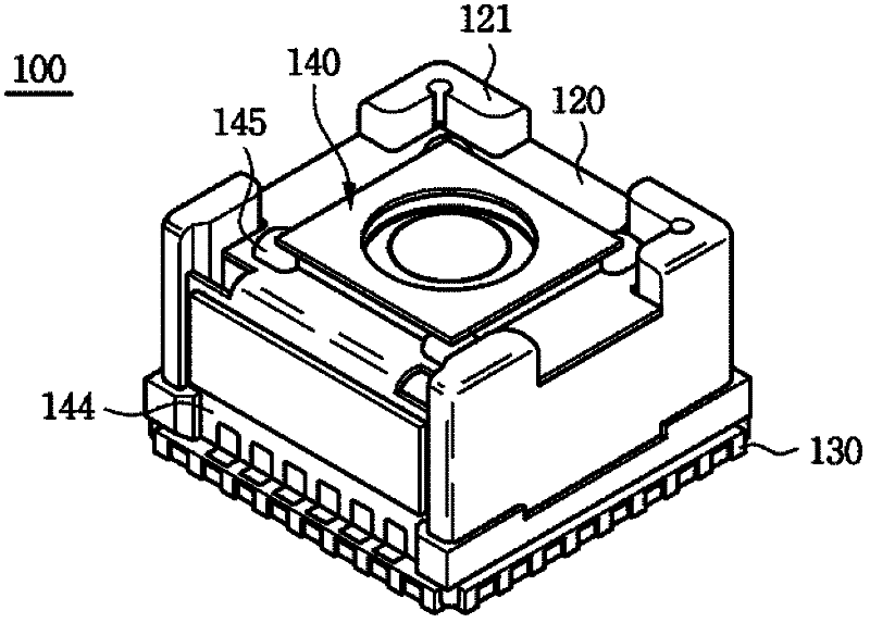
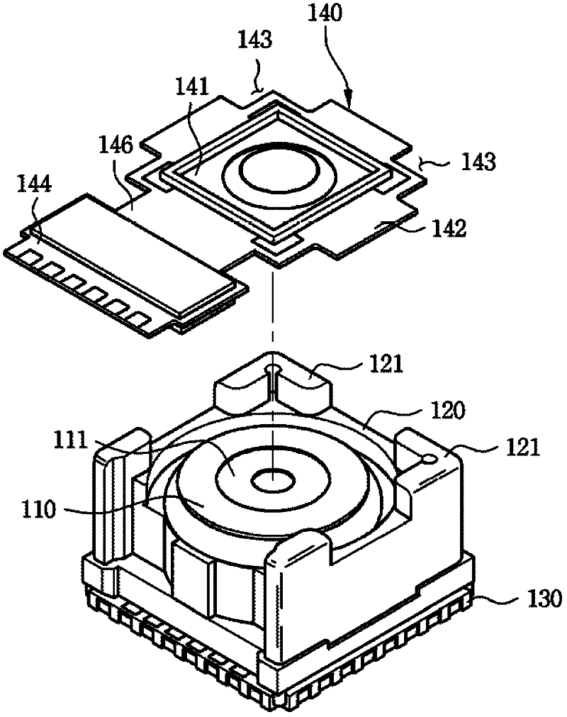
Disclosed herein is a camera module including: a lens barrel having a lens mounted thereon; a housing having the lens barrel received therein; a printed circuit board connected to a lower portion of the lens barrel and fixed to the housing; and an LC lens module including an LC lens having the center positioned on the same axis as the center of the lens and coupled to the housing. The LC lens is positioned so as to correspond to the center axis of the lens, such that auto-focusing may be efficiently and stably implemented, and electrical connection parts coupling the LC lens to the LC lens module are exposed to the outside of the housing, such that a connection state may be checked with the naked eyes and additional repair may be easily and simply performed.

Description

[0001] Cross References to Related Applications [0002] This application claims the priority of Korean Patent Application No. 10-2010-0137808, filed on December 29, 2010, and entitled "Camera Module (camera module)", the entire content of which is hereby incorporated by reference incorporated into this application. technical field [0003] The invention relates to a camera module. Background technique [0004] In recent years, as the ratio of smartphones with various displays and application software has increased among mobile communication terminals, there has been an increasing demand for downsizing modules for high-density mounting inside components and for high-spec hardware modules. [0005] Therefore, as a camera module for a mobile communication terminal, a high-pixel autofocus module having a small size and a thin structure and capable of shooting a video has been developed. [0006] In particular, the lens-driven autofocus module according to the related art is l...

Claims


Application Information

Patent Timeline
Patent Type & Authority Applications(China)
IPC IPC(8): G02B7/09
CPCG03B3/10G02B13/0085G03B17/12H04N5/2254G02B7/08H04N5/2257G02F1/133H04N23/57H04N23/55
Inventor 高永镐
Owner SAMSUNG ELECTRO MECHANICS CO LTD
Why Eureka
Try Eureka