Method of and apparatus for detecting cracks in piezoelectric element

A piezoelectric element and detection unit technology, applied in the measurement of electrical variables, measurement devices, material analysis by electromagnetic means, etc. Piezoelectric element cracks and other problems

Active Publication Date: 2012-07-11
NHK SPRING CO LTD
View PDF7 Cites 12 Cited by
  • Summary
  • Abstract
  • Description
  • Claims
  • Application Information

AI Technical Summary

Problems solved by technology

[0012] But these related techniques cannot easily detect microcracks in piezoelectric elements, or these related techniques are practically difficult to implement
That is, in practice, these related techniques cannot definitely find cracks in piezoelectric elements, including microcracks

Method used


Image

  • Method of and apparatus for detecting cracks in piezoelectric element
  • Method of and apparatus for detecting cracks in piezoelectric element
  • Method of and apparatus for detecting cracks in piezoelectric element

Examples


Embodiment Construction

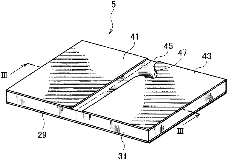
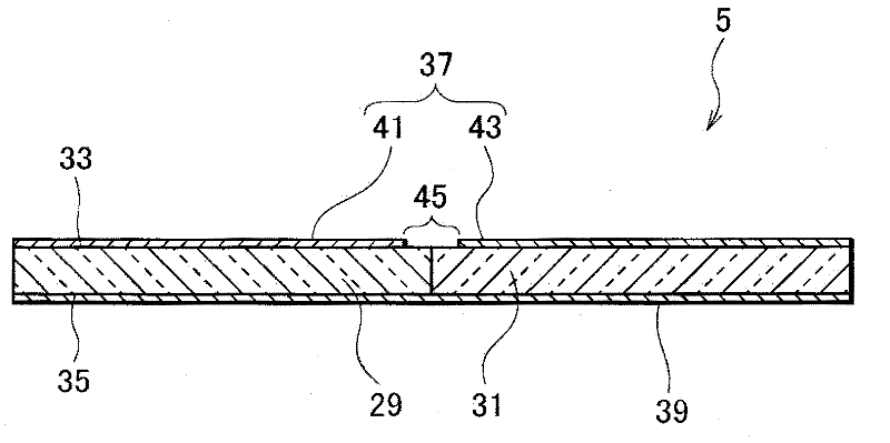
[0030] Embodiments of the present invention will be described with reference to the drawings. Each embodiment applies a voltage at the resonant frequency of the piezoelectric element through the electrodes, the piezoelectric element is interposed between the electrodes, the dielectric loss tangent between the electrodes is measured under the applied voltage, and according to the measured dielectric Loss tangent, detects whether the piezoelectric element has one or more cracks (hereinafter simply referred to as "cracks").

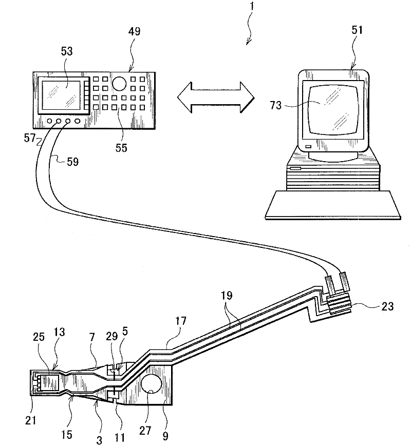
[0031] figure 1 is a schematic view showing the apparatus for detecting a crack in a piezoelectric element and the head suspension 3 according to the first embodiment of the present invention.

[0032] figure 1 , the crack detection apparatus 1 detects whether or not the piezoelectric element 5 fitted in the head suspension 3 has a crack. First, examples of the piezoelectric element 5 and the head suspension 3 will be described.

[0033] The head suspens...


PUM


Abstract

A method and an apparatus for detecting cracks in piezoelectric element. A method detects one or more cracks in a piezoelectric element interposed between a pair of electrodes and deforms according to a voltage applied thereto through the pair of electrodes. The method includes steps of applying a voltage at least at a resonance frequency of the piezoelectric element to the piezoelectric element through the pair of electrodes, measuring a dielectric tangent between the pair of electrodes under the applied voltage, and detecting if there are cracks in the piezoelectric element according to the measured dielectric tangent. The dielectric tangent of the piezoelectric element at the resonance frequency has a large peak or no peak depending on whether or not the piezoelectric element has cracks. Accordingly, the method easily and surely detects if the piezoelectric element has cracks according to the dielectric tangent of the piezoelectric element measured at the resonance frequency.

Description

technical field [0001] The present invention relates to a method and an apparatus for detecting cracks in a piezoelectric element deformed according to a voltage applied thereto. Background technique [0002] Small precision information devices are developing rapidly, and for use with such devices, there is an increased need for microactuators capable of positional control over very small distances. For example, optical systems for calibrating focus and tilt angles, inkjet printers for controlling inkjet heads, and disk drives for controlling magnetic heads are highly in need of the microactuators. [0003] Disk drives increase storage capacity by increasing the number of tracks per inch (TPI), that is, by narrowing the width of each track on the disk. [0004] Therefore, high-capacity disk drives require actuators that can precisely position the head across the track within a minute range. [0005] In order to meet this need, Japanese Unexamined Patent Application Publica...

Claims


Application Information

Patent Timeline
Patent Type & Authority Applications(China)
IPC IPC(8): G01N27/00G01N27/20
CPCG01N27/02G01R29/22
Inventor 古田英次郎荒井肇
Owner NHK SPRING CO LTD
Why Eureka
Try Eureka