Glass substrate defect inspection device and glass substrate defect inspection method

A technology for inspection of glass substrates and defects, applied in measuring devices, optical devices, and material analysis through optical means, can solve problems such as no public solutions, jumping of the front end of the glass substrate, and no public solutions to problems, etc. Achieve high-precision inspection and ensure flatness

Inactive Publication Date: 2012-07-11
HITACHI HIGH-TECH CORP
View PDF10 Cites 6 Cited by
  • Summary
  • Abstract
  • Description
  • Claims
  • Application Information

AI Technical Summary

Problems solved by technology

[0004] The above-mentioned method of transporting glass substrates by air levitation has the following problems: due to the inertia during transport, the front end of the glass substrate jumps, etc., thereby losing the flatness in the transport direction, and the inspection accuracy is not high.
[0005] Although Patent Document 1 discloses that glass substrates are transported and processed after stopping, the above-mentioned problems when inspections are performed during transport are not recognized, and solutions to the problems are not disclosed.
In addition, although an optical inspection device is disclosed in Patent Document 2, the above-mentioned problem of inspection during transportation is not recognized, and no solution is disclosed.

Method used


Image

  • Glass substrate defect inspection device and glass substrate defect inspection method
  • Glass substrate defect inspection device and glass substrate defect inspection method
  • Glass substrate defect inspection device and glass substrate defect inspection method

Examples


Embodiment Construction

[0024] Hereinafter, embodiment of the glass substrate defect inspection apparatus of this invention is demonstrated based on drawing.

[0025] figure 1 It is a block diagram showing the first embodiment of the glass substrate defect inspection apparatus 100 . The glass substrate defect inspection apparatus 100 roughly includes: an inspection unit 10 for inspecting a glass substrate P; unit 40; an air supply and suction unit 50 including a compressed air supply source 51 for supplying compressed air to the transport unit 40 and a vacuum supply source 52 for sucking in air; and an overall control unit 60 for monitoring and controlling the status of each part.

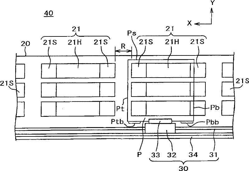
[0026] figure 2 It is a figure which shows the schematic structure seen from the upper part of the conveyance part 40 which concerns on 1st Embodiment of this invention. The air suspension stage 20 has a plurality of rectangular divided stages 21 arranged in the conveyance direction (X) and the direction Y perpendicul...


PUM


Abstract

A glass substrate defect inspecting device and an inspection method thereof are provided to reduce or remove bouncing phenomenon and steadily perform an inspection by reducing the corrected amount during the inspection. A glass substrate (100) comprises a lifting device, a transfer device, and an optical inspection device. The lifting device lifts up a glass substrate(P) using air. The transfer device transfers the glass substrate to an inspection area where the lifting device is absent. The optical inspection device takes a picture of the glass substrate, thereby performing an inspection. A glass substrate defect inspecting device comprises a reduction device. The reduction device reduces the displacement caused by the bouncing of an end part of the glass substrate toward a transferring direction.

Description

technical field [0001] The present invention relates to a glass substrate defect inspection device and a glass substrate defect inspection method, and relates to a glass substrate defect inspection device and a glass substrate defect inspection method capable of inspecting with high precision. Background technique [0002] A liquid crystal display panel or a solar cell panel is manufactured by forming a pattern on a glass substrate using a photolithography technique or the like. At this time, if there are defects such as damage or foreign matter on the surface of the glass substrate, it will not be possible to form a pattern satisfactorily, which will cause a defective product. Therefore, conventionally, defect inspections of glass substrate surface damage, foreign matter, and the like have been performed using defect inspection apparatuses. [0003] In order to carry out defect inspection, it is necessary to convey and inspect a glass substrate to a defect inspection appar...

Claims


Application Information

Patent Timeline
IPC IPC(8): G01N21/958
CPCG01B11/306G01N21/896G01N21/956G01N21/958G02F1/1309
Inventor 荒木正树广井修一衣川耕平
Owner HITACHI HIGH-TECH CORP
Why Eureka
Try Eureka