
Measuring apparatus and measuring method

A technology of measuring device and measuring method, which is applied in the direction of measuring device, optical device, photo-plate making process exposure device, etc., can solve the problems of increasing the length of long reflectors, avoid processing and manufacturing difficulties, and realize high-precision measurement Effect

Active Publication Date: 2012-07-11
SHANGHAI MICRO ELECTRONICS EQUIP (GRP) CO LTD
View PDF6 Cites 8 Cited by
  • Summary
  • Abstract
  • Description
  • Claims
  • Application Information

AI Technical Summary

Problems solved by technology

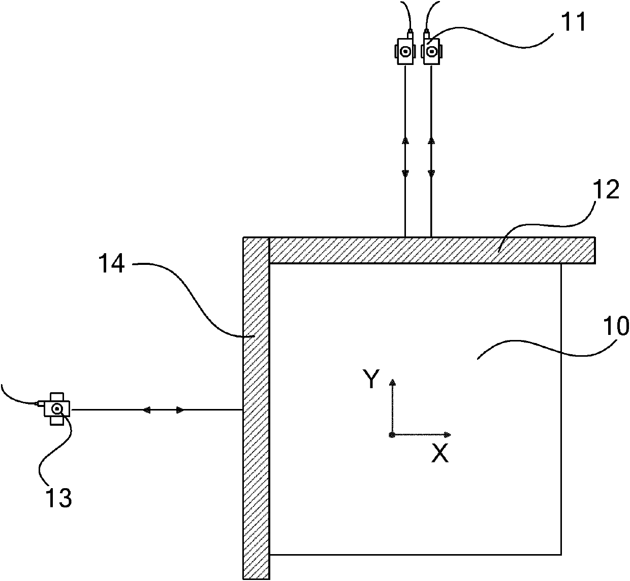
[0004] U.S. Patent US6285457B2 proposes an interferometer layout scheme for measuring the three-dimensional vertical direction and rotational position (X, Y, Z, Rx, Ry, Rz) of the workpiece table. Although it can achieve high-precision positioning, it still cannot solve the problem of With the increase of the table stroke, the length of the long reflector also increases

Method used


Image

  • Measuring apparatus and measuring method
  • Measuring apparatus and measuring method
  • Measuring apparatus and measuring method

Examples


Embodiment Construction

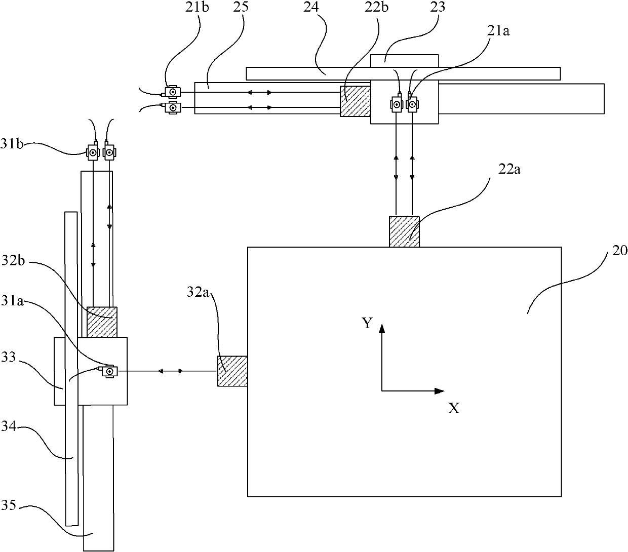
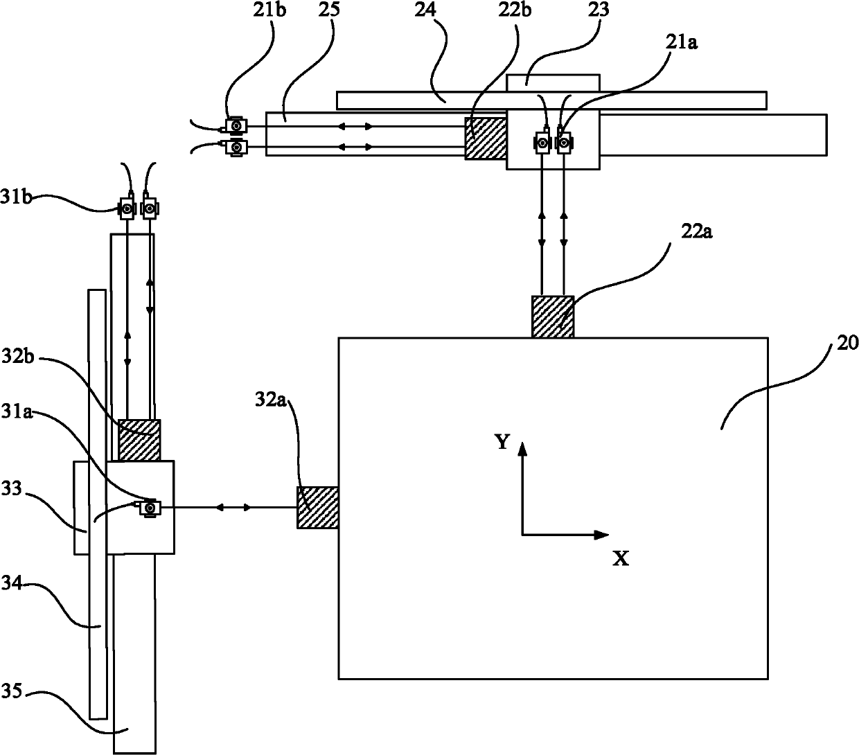
[0028] The measurement device and method proposed by the present invention will be further described in detail below in conjunction with the accompanying drawings and specific embodiments. It should be noted that all the drawings are in very simplified form, and are only used for the purpose of conveniently and clearly assisting in describing the embodiments of the present invention.

[0029] Such as figure 2 As shown, the present invention provides a measuring device, which is applied to the precision motion and position measurement of a long (large) stroke workpiece table in a lithography machine system, including a first direction measurement system and a second direction measurement system perpendicular to each other. In the following descriptions, the "X direction" is set as the "first direction", and the "Y direction" is set as the "second direction".

[0030] The Y-direction measurement system includes: a Y-direction mobile interferometer 21a, including 2 interferomet...


PUM


Abstract

The invention provides a long-travel workpiece table measuring apparatus and a measuring method. The measuring apparatus comprises two sets of measuring systems which are perpendicular to each other and are applied on a first direction and a second direction, movable interferometers and workpiece table reflectors in the measuring systems respectively monitor and measure the moving positions of a workpiece table along the first direction or the second direction, and fixed interferometers and interferometer reflectors in the measuring systems are utilized to compensate the error of the moving position of the workpiece table measured by the movable interferometers and the workpiece table reflectors. The difficulty of processing and manufacturing large-size strip-shaped reflectors is avoided, and the high-precision measurement of the long-travel position of the workpiece table is realized.

Description

technical field [0001] The invention relates to the application field of photolithography machine systems, and in particular to a measuring device and method applied to the stroke position of a workpiece table of a photolithography machine. Background technique [0002] In the front-end manufacturing equipment of large-scale semiconductor integrated circuits, the lithography machine is the most complex and demanding equipment, and the workpiece table is a very important structure in the lithography machine equipment, providing a carrier capable of precise positioning and rapid movement object platform. In plane motion, three parameters need to be controlled: X-direction movement, Y-direction movement and rotation R around the Z-axis Z . At present, in the existing lithography machine, the travel position of the workpiece table is mainly obtained by placing a long strip mirror on the workpiece table, and controlling the two-axis interferometer that is vertical to each other...

Claims


Application Information

Patent Timeline
Patent Type & Authority Applications(China)
IPC IPC(8): G01B11/00G03F7/20
Inventor 唐广繁韩良华
Owner SHANGHAI MICRO ELECTRONICS EQUIP (GRP) CO LTD
Learn More