Detection and ranging apparatus and detection and ranging method

A technology of distance measuring device and computing device, which can be applied to measuring devices, radio wave measuring systems, instruments, etc., and can solve the problems of time shift, reduction of detection distance, and signal deterioration

Inactive Publication Date: 2009-04-01
FUJITSU LTD +1
View PDF3 Cites 19 Cited by
  • Summary
  • Abstract
  • Description
  • Claims
  • Application Information

AI Technical Summary

Problems solved by technology

[0008] However, switching from one antenna to another with a switch has negative effects such as degraded signal and reduced detection distance
Also, since the waves transmitted from multiple transmit antennas and returned due to reflection are not simultaneously received by multiple receive antennas, the problem arises that time and phase shifts occur
This problem can be alleviated by increasing the switching speed, but there is an inherent limit to the switching speed

Method used


Image

  • Detection and ranging apparatus and detection and ranging method
  • Detection and ranging apparatus and detection and ranging method
  • Detection and ranging apparatus and detection and ranging method

Examples


Embodiment Construction

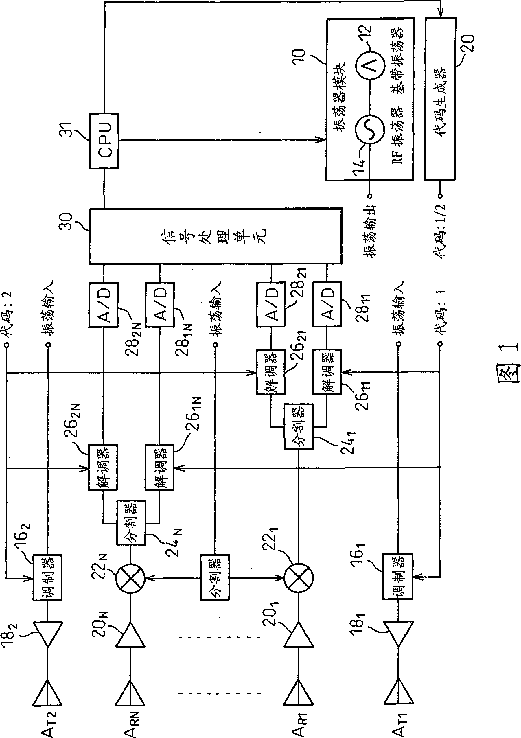
[0020] FIG. 1 shows a radar device according to one embodiment of the invention. The embodiment shown in Fig. 1 is similar to that in JP 2006-98181A, using N antenna elements A R1 to A RN The receiving array antenna and the two sides of the receiving array antenna include 2 (M=2) antenna elements A T1 and A T2 transmitting array antenna.

[0021] An oscillator module (oscillator module) 10 includes an oscillator 12 and a voltage-controlled RF (radio frequency) oscillator 14 for generating a baseband signal (such as a triangle wave), the frequency of the voltage-controlled RF oscillator 14 is controlled by the output of the oscillator 12, and the oscillation The transmitter module 10 generates a transmission wave whose frequency is modulated by the triangular wave. The code generator 20 generates two PN codes 1 and 2 that are orthogonal to each other. In Modulator 16 1 and 16 2 Among them, using PN codes 1 and 2, binary phase-shift keying (BPSK) spread spectrum is direct...


PUM


Abstract

In a detection and ranging apparatus that performs direction-of-arrival estimation using a sensor array and that enlarges an effective aperture using a plurality of transmitting sensors, adverse effects associated with time division switching are eliminated, achieving high-accuracy measurement. A transmitter wave is spread in modulators by using mutually orthogonal codes, and the resulting transmitter waves are radiated from two transmitting sensors. Signals received by receiving sensors are each split by a splitter into two parts, which are then respectively despread in a demodulator by using the same codes as those used in the transmitter.

Description

technical field [0001] The present invention relates to a detection and ranging device and a detection and ranging method having a function of estimating a signal arrival direction by using a sensor array and an arrival direction estimation method. Background technique [0002] As an example of such a detection and ranging device, a radar device capable of estimating all three quantities of a relative distance, a relative velocity, and an angular bearing of a target can be considered. In radar, a sensor is an antenna. FW-CW radar is a type of radar that projects forward a transmitted wave frequency-modulated by a triangular wave, etc., receives a reflected wave from a target, mixes the reflected wave with a part of the transmitted signal in a mixer, and obtains a signal containing The baseband signal of the target information, and the distance and relative speed are calculated from the baseband signal, and this type of radar is commercially realized as an automotive radar, ...

Claims


Application Information

Patent Timeline
Patent Type & Authority Applications(China)
IPC IPC(8): G01S13/34G01S13/28
CPCG01S13/87G01S13/325G01S13/34G01S7/032G01S13/931G01S2013/0254
Inventor 白川和雄大口胜之近藤泰幸
Owner FUJITSU LTD
Why Eureka
Try Eureka