Cloth outlet swing mechanism

A cloth-discharging roller and cloth-roller technology, applied in the field of textile machinery, can solve the problems of difficult operation by operators, equipment damage, and increased static electricity on the cloth surface.

Inactive Publication Date: 2012-07-11
高国涛
View PDF0 Cites 9 Cited by
  • Summary
  • Abstract
  • Description
  • Claims
  • Application Information

AI Technical Summary

Problems solved by technology

Or increase the wrap angle of the cloth on the cloth outlet roller by increasing the cloth guide roller to prevent slipping. As a result, the static electricity on the cloth surface increases, which is not only difficult for the operator to operate, but also easily causes the cloth surface to be attracted and wound on the cloth outlet roller, causing equipment damage

Method used


Image

  • Cloth outlet swing mechanism
  • Cloth outlet swing mechanism

Examples


Embodiment Construction

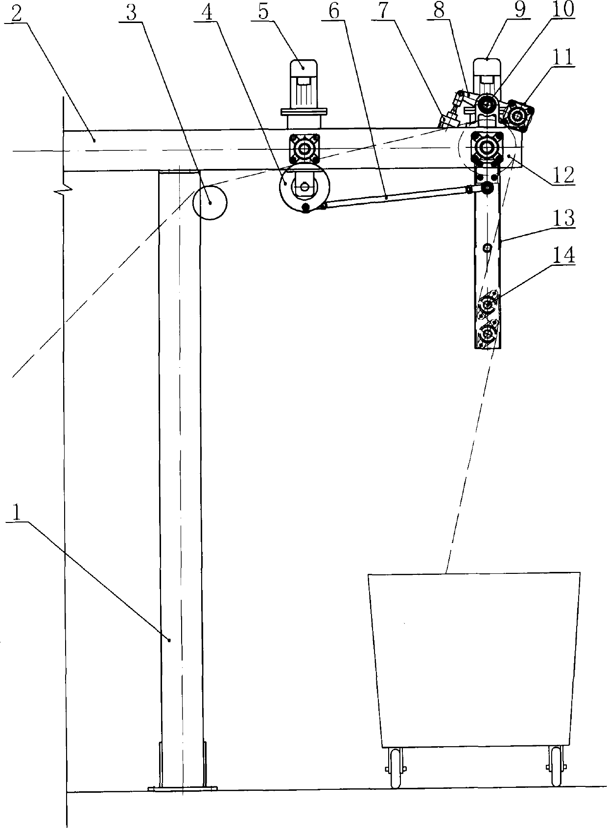
[0008] Such as figure 1 As shown, the swinging cloth delivery mechanism of the present invention includes a column 1 and a crossbeam 2 connected to the top of the column 1. A swing motor 5 and a cloth discharge motor 9 are installed on the beam 2. The swing motor 5 drives the swing wheel 4 to rotate, and the swing wheel 4 A swing arm pull rod 6 is hinged on the circumference of the swing arm pull rod 6, and the other end of the swing arm pull rod 6 is hinged on the upper end of the swing arm 13, and a cloth guide rod 14 is installed on the lower end of the swing arm 13, and the swing arms 13 on both sides are respectively hinged on the cloth outlet roller 12. Two shaft ends; the cloth outlet motor drives the cloth outlet roller 12 to rotate, the cloth outlet roller 12 is pressed with a pressure roller 11, and the two ends of the pressure roller 11 are installed with a rocker arm 8, and the middle part of the rocker arm 8 is hinged on the swing arm through a hinge shaft 10 The ...


PUM


Abstract

The invention discloses a cloth outlet swing mechanism, which belongs to the technical field of spinning machinery and comprises a vertical column and a crossbeam connected on the top of the vertical column. The cloth outlet swing mechanism is characterized in that a cloth swing motor and a cloth outlet motor are mounted on the crossbeam, the cloth swing motor drives a cloth swing wheel to rotate, a swing arm pull rod is hinged on the circumference of the cloth swing wheel, the other end of the swing arm pull rod is hinged at the upper end of a swing arm, a cloth guide rod is mounted at the lower end of the swing arm, and two axial ends of a cloth outlet roll are hinged on two sides of the swing arm. The cloth outlet motor drives the cloth outlet roll to rotate, a press roll is pressed on the cloth outlet roll, rocker arms are mounted at two ends of the press roll, the middles of the rocker arms are hinged at the upper end of the swing arm through hinge shafts, and the other ends of the rocker arms are hinged with one end of a piston rod of an air cylinder. Cloth is wound on the cloth outlet roll and pressed by the press roll, so that the cloth and the cloth outlet roll can rotate synchronously without slipping during cloth outlet, the pressure of the press roll can be controlled by adjusting pressure of the air cylinder and damage to the cloth outlet roll due to overlarge pressure is avoided.

Description

technical field [0001] The invention relates to a swinging cloth discharging mechanism, which belongs to the technical field of textile machinery. Background technique [0002] In the finishing process of printing and dyeing, the equipment for feeding and exiting cloth in open width uses the cloth outlet mechanism, and the cloth is mainly driven by the rotation of the cloth outlet roller. For relatively smooth cloth, due to the small friction between the cloth surface and the surface of the cloth outlet roller, it is easy to form slippage. Therefore, the surface of the cloth outlet roller is often coated with grain rubber to increase friction. Or increase the wrap angle of the cloth on the cloth outlet roller by increasing the cloth guide roller to prevent slipping. As a result, the static electricity on the cloth surface increases, which is not only difficult for the operator to operate, but also easily causes the cloth surface to be attracted and wound on the cloth outle...

Claims


Application Information

Patent Timeline
IPC IPC(8): D06B23/04
Inventor 高国涛
Owner 高国涛
Why Eureka
Try Eureka