Liquid-crystal display device

A technology of liquid crystal display device and liquid crystal layer, which is applied in the direction of instruments, optics, optical components, etc., and can solve problems such as decreased contrast, low contrast, and increased light quantity

Active Publication Date: 2012-07-04
SHARP KK
View PDF12 Cites 15 Cited by
  • Summary
  • Abstract
  • Description
  • Claims
  • Application Information

AI Technical Summary

Problems solved by technology

If this useless reflection is not prevented, even if the display device realizes a substantially completely black display in a dark room environment, when viewed in a bright room environment, the amount of light at the time of black display of the display device increases, resulting in a decrease in contrast.
[0009] As mentioned above, in the circularly polarized light VA mode using a circular polarizing plate, although the transmittance improvement effect and the unnecessary reflection prevention effect can be obtained, in the conventional circularly polarized light VA mode liquid crystal display device, the There is still room for improvement in that the contrast ratio is low and sufficient viewing angle characteristics cannot be obtained.

Method used


Image

  • Liquid-crystal display device
  • Liquid-crystal display device
  • Liquid-crystal display device

Examples


no. 1 approach

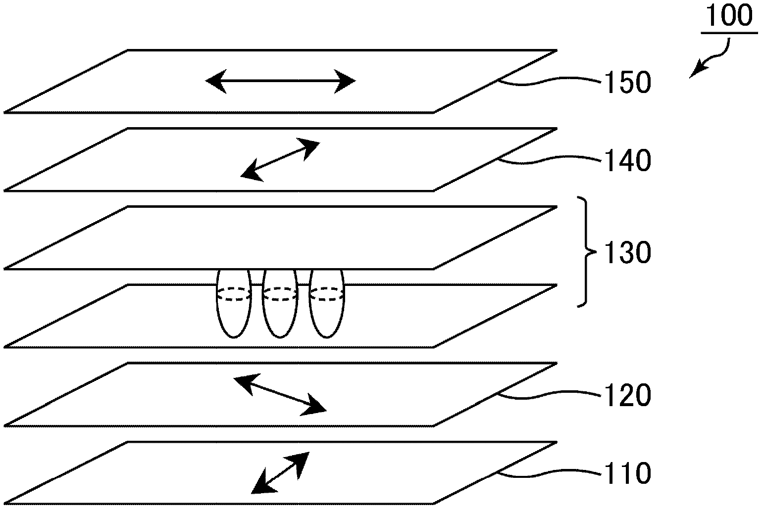
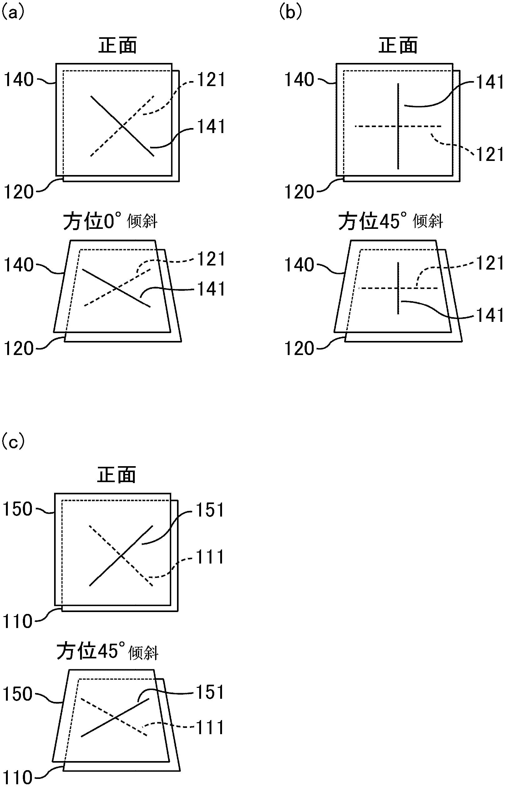
[0168] refer to Figure 21 , the first embodiment of the liquid crystal display device to which the present invention is applied will be described. Figure 21 is a schematic cross-sectional view showing the structure of the liquid crystal display device according to the first embodiment of the present invention.

[0169] The liquid crystal display device according to the first embodiment of the present invention is, for example, Figure 21 Shown is a circularly polarized light VA mode liquid crystal display device, the liquid crystal display device sequentially stacks the first polarizer 11, the first λ / 4 plate (the first birefringent layer) 12, the VA mode liquid crystal unit 10, and the third The first kind of birefringent layer 13, the second λ / 4 plate 14, the second kind of birefringent layer 15 and the second polarizer 16 are obtained.

[0170] The liquid crystal cell 10 is configured to include: first and second transparent substrates 1r, 1f; and a liquid crystal layer...

no. 2 approach

[0172] refer to Figure 22 A second embodiment of a liquid crystal display device to which the present invention is applied will be described. Figure 22 is a schematic cross-sectional view showing the structure of a liquid crystal display device according to a second embodiment of the present invention.

[0173] The liquid crystal display device according to the second embodiment of the present invention is, for example, Figure 22 Shown is a circularly polarized light VA mode liquid crystal display device. The liquid crystal display device is sequentially laminated with a first polarizer 11, a first λ / 4 plate (the first birefringent layer) 12, a VA mode liquid crystal unit 10, and a second polarizer. λ / 4 plate 14, second birefringent layer 15 and second polarizer 16 are obtained.

[0174] The second embodiment of the present invention is the same as the first embodiment except that the third birefringent layer is not included, and thus detailed description thereof will be ...

Embodiment 1

[0209] As Example 1, the same liquid crystal display device as in the first embodiment of the present invention was actually manufactured. Various parameters such as optical parameters (phase difference and its wavelength dispersion) are summarized in Tables 4 and 5 together with parameters of other examples.


PUM

PropertyMeasurementUnit
wavelengthaaaaaaaaaa
reflectivityaaaaaaaaaa
heightaaaaaaaaaa

Abstract

Provided is a liquid-crystal display device having a high contrast ratio over a wide viewing angle range and having little coloration occurring when black is displayed. The liquid-crystal display device has, in this order, a polarizer, a first [lambda] / 4 plate satisfying the condition nx > ny >= nz, a vertically oriented liquid-crystal cell, a second [lambda] / 4 plate having a substantially same Nz coefficient as the first [lambda] / 4 plate and satisfying the condition nx > ny >= nz, a double refraction layer satisfying the condition nx < ny <= nz, and another polarizer. The liquid-crystal cell has a liquid-crystal layer and blue, green, and red CF layers and satisfies at least one of the following equations. R(B) / R(G) > [delta]n(B) / [delta]n(G) R(R) / R(G) < [delta]n(R) / [delta]n(G) In the equation, R(B), R(G), and R(R) indicate retardations in the thickness direction of the liquid-crystal cell at wavelengths of 450nm, 550 nm, and 650 nm, respectively, and [delta]n(B), [delta]n(G), and [delta]n(R) indicate the double refractions of a liquid-crystal material of the liquid-crystal layer at wavelengths of 450nm, 550 nm, and 650 nm, respectively.

Description

technical field [0001] The present invention relates to a liquid crystal display device. More specifically, it relates to a VA (vertical alignment) mode liquid crystal display device using a circular polarizing plate. Background technique [0002] Liquid crystal display devices are widely used as display devices of various information processing devices typified by computers and television receivers. In particular, TFT-type liquid crystal display devices (hereinafter also referred to as "TFT-LCD") are expected to spread widely and further expand the market, and along with this, further improvement in image quality is desired. Hereinafter, TFT-LCD is taken as an example for description, but the present invention is not limited to TFT-LCD, and is applicable to common liquid crystal display devices, for example, liquid crystal display devices of simple matrix method and plasma addressing method. [0003] So far, the most widely used method in TFT-LCD is the so-called TN (twis...

Claims


Application Information

Patent Timeline
Patent Type & Authority Applications(China)
IPC IPC(8): G02F1/13363G02F1/1335
CPCG02F2413/03G02F2202/40G02F2001/133541G02F2203/04G02F1/13363G02F1/133371G02F2413/14G02F2001/133637G02F2001/133742G02F1/133514G02F2413/13G02F2413/06G02F1/1335G02F2413/04G02F1/133634G02F2203/64G02F2413/12G02F2413/11G02F2001/133638G02F1/1393G02F1/133502G02B1/118G02F1/133541G02F1/133637G02F1/133638G02F1/133742
Inventor 坂井彰樱木一义长谷川雅浩
Owner SHARP KK
Why Eureka
Try Eureka