Device for boundary layer gettering and composite component therefor

A composite component and boundary layer technology, applied in boundary layer control, aircraft parts, transportation and packaging, etc., can solve problems such as influence, long manufacturing time, and stringer-consuming manufacturing technology, and achieve high quality and reduce manufacturing time.

Inactive Publication Date: 2016-02-24
AIRBUS OPERATIONS GMBH
View PDF7 Cites 0 Cited by
  • Summary
  • Abstract
  • Description
  • Claims
  • Application Information

AI Technical Summary

Problems solved by technology

[0008] In this case, the rather complex and extensive laser welding of the individual stringers has a disadvantageous effect on production technology
resulting in long manufacturing times

Method used


Image

  • Device for boundary layer gettering and composite component therefor
  • Device for boundary layer gettering and composite component therefor
  • Device for boundary layer gettering and composite component therefor

Examples


Embodiment Construction

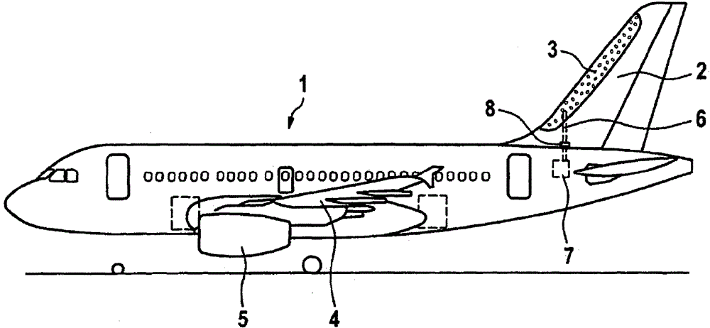
[0027] according to figure 1 , in the region of the vertical tail 2 there is an absorbable surface 3 on the outer skin 1 of the civil aircraft shown here by way of example. In addition, similar absorbable surfaces, not shown in further detail, are provided on the other aerodynamic components, here on the wing 4 and on the nacelle 5 , for the boundary Components of the device for layer gettering.

[0028] The suction surface 3 of the vertical stabilizer 2 is connected via a suction line 6 shown here only schematically to a suction source 7 which generates the necessary negative pressure to suck off the air on the surface 3. boundary layer. To adjust the air mass flow, a perforated plate 8 is inserted into the suction line 6 of the device for boundary layer suction.

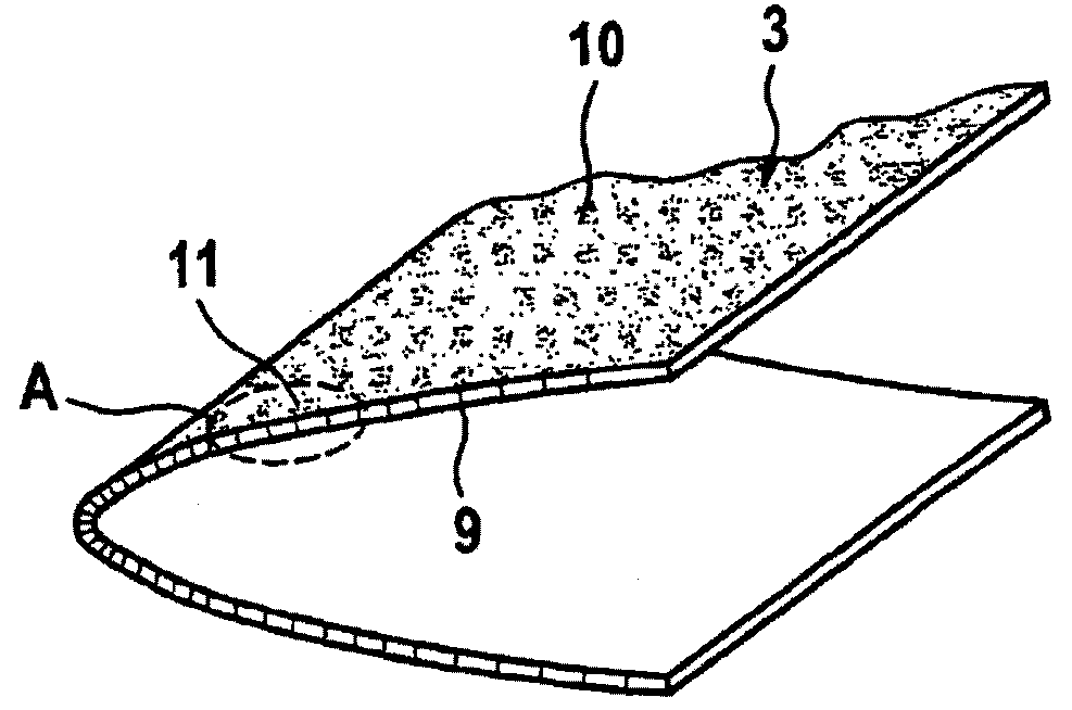
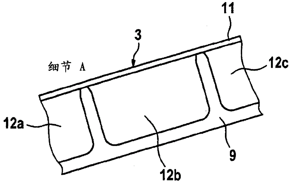
[0029] The position of the absorbable surface 3 of the vertical stabilizer 2 not shown in further detail figure 2 The section shown in has a surface penetrated by the smallest through-hole 10 of about 40 μm to...


PUM


Abstract

The invention relates to a device for boundary layer suction on the outer skin (1) of an aircraft, on which device an absorbent surface (3) pierced by a through hole (10) passes through at least one A suction duct (6) is connected to a suction source (7), wherein the suction surface (3) is formed by at least one plate-shaped composite component formed by forming a plurality of outward facing skins (1) The suction channel (12a-12c) is made of an extruded profile (9) made of light metal as a base body, on which a microperforated cover is mounted in the region of the suction surface (3) A plate (11) for forming the outer skin (1). Furthermore, the invention also relates to a method for producing such a panel-shaped composite component.

Description

technical field [0001] The invention relates to a device for boundary layer suction on the outer skin of an aircraft, in which a suction surface penetrated by a through-opening is connected to a suction source via at least one suction duct. Furthermore, the invention relates to a composite component for forming such a gettering surface and a method for producing the composite component. Background technique [0002] The field of application of the invention extends to aircraft construction, in particular with regard to large civil aircraft. Aerodynamic components of such civil aircraft, such as nacelles, wings or vertical tails, can be provided with devices for boundary layer suction on the outer skin in order to reduce frictional drag. In an airfoil, the airflow accelerates after passing through the greatest curvature and then slows down again. Here, the boundary layer loses kinetic energy and thickens. At the point of transition, the boundary layer changes from laminar ...

Claims


Application Information

Patent Timeline
Patent Type & Authority Patents(China)
IPC IPC(8): B64C21/06
CPCB64C5/06B64C21/06B64C2230/22Y02T50/10Y10T29/49826
Inventor 马丁·格贝尔
Owner AIRBUS OPERATIONS GMBH
Why Eureka
Try Eureka