
Method for redundant backup of network equipment, and routing equipment and system

A technology of redundant backup and network equipment, applied in the field of communication, can solve the problems such as the failure of the VRRP protocol to operate normally and the inability to forward VRRP packets.

Inactive Publication Date: 2012-07-04
HUAWEI TECH CO LTD
View PDF5 Cites 11 Cited by
  • Summary
  • Abstract
  • Description
  • Claims
  • Application Information

AI Technical Summary

Problems solved by technology

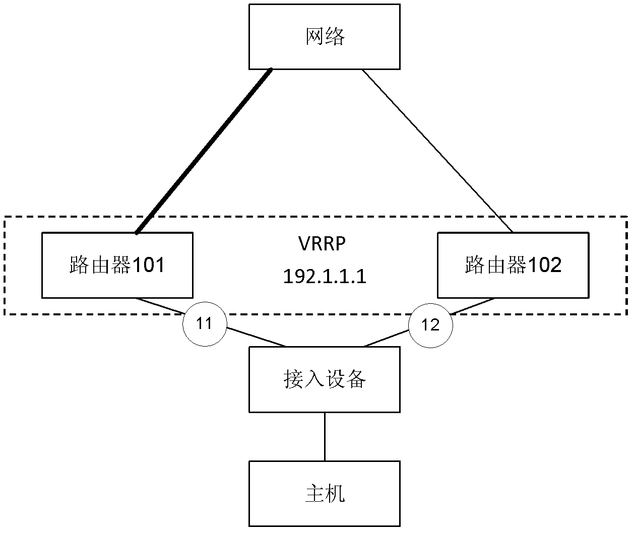
[0006] The embodiment of the present invention provides a method, routing device and system, which solves the problem in the prior art that the VRRP protocol cannot run normally because the user access device cannot forward the VRRP message.

Method used


Image

  • Method for redundant backup of network equipment, and routing equipment and system
  • Method for redundant backup of network equipment, and routing equipment and system
  • Method for redundant backup of network equipment, and routing equipment and system

Examples


Embodiment 1

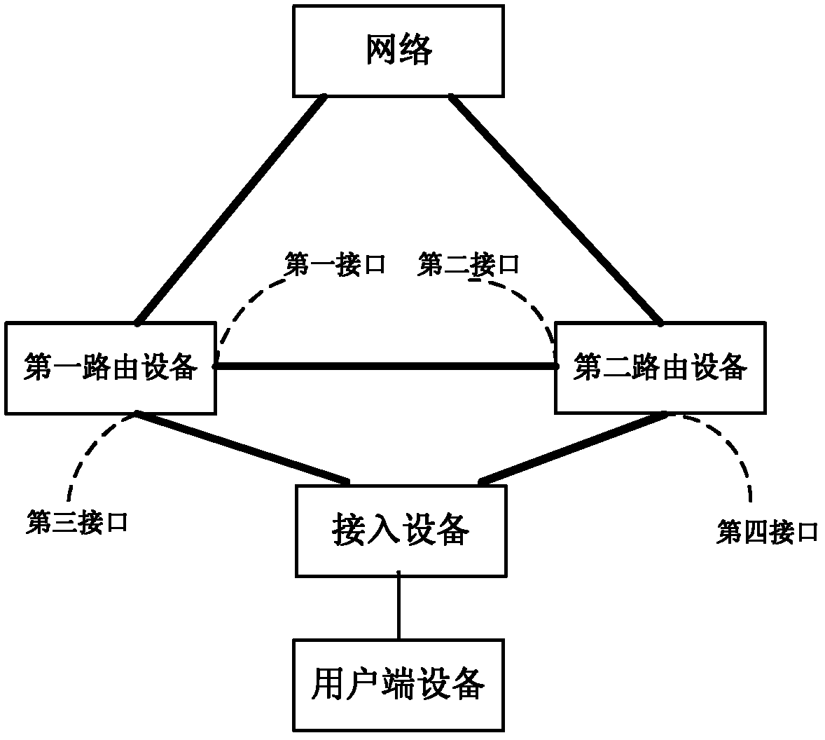
[0049] figure 2 It is a networking diagram of Embodiment 1 of the present invention. The first routing device includes a first interface and a third interface, and the second routing device includes a second interface and a fourth interface. The first interface is directly connected to the second interface. The direct connection It refers to connecting through a direct connection line (or heartbeat line); the first routing device communicates with the access device through the third interface, and the second routing device communicates with the access device through the fourth interface.

[0050] The first routing device and the second routing device can be a router in terms of equipment form, or a switch with a layer-3 switching function; from the networking position, it can be a network-side provider edge router (Network-Provider Edge, NPE) , may also be a service router (Service Router, SR), and may also be a broadband remote access server (Broadband Remote Access Server, ...

Embodiment 2

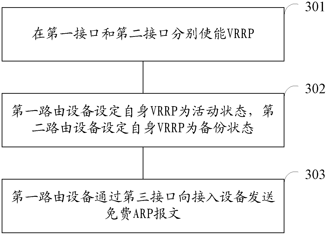
[0073] A network device redundancy backup system provided by an embodiment of the present invention includes: a first routing device and a second routing device running VRRP to form a VRRP backup group. In this embodiment, the primary and backup VRRP devices are determined according to the VRRP priority, and the VRRP device with high priority is used as the primary device. It is assumed that the first routing device has a higher priority than the second routing device in the initial state, so after initialization, set The VRRP state of the first routing device is an active state, and the VRRP state of the second routing device is set as a backup state.

[0074] Please refer to Figure 4 and Figure 5 , the first routing device includes a first interface and a third interface, the second routing device includes a second interface and a fourth interface, the first interface and the second interface are directly connected, and the direct connection refers to a direct connection ...


PUM


Abstract

The embodiment of the invention discloses a method for the redundant backup of network equipment. The method comprises the following steps that: VRRP (Virtual Router Redundancy Protocol) messages are exchanged through direct communication between a VRRP active router and a VRRP standby router so as to negotiate active-standby relationship, and meanwhile, the VRRP active router sends a free ARP (Address Resolution Protocol) message to access equipment through being connected with an interface of the access equipment, and informs the access equipment of guiding user flows to the VRRP active router. The embodiment of the invention further provides corresponding equipment and system. According to the technical scheme provided by the embodiment of the invention, the VRRP messages are exchanged through the direct communication between the VRRP active router and the VRRP standby router, and the VRRP active router sends the free ARP (Address Resolution Protocol) message to the access equipment through being connected with the interface of the access equipment, so that the problem that the VRRP cannot be normally operated because the access equipment cannot forward the VRRP messages, in the prior art, is solved.

Description

technical field [0001] The invention relates to the technical field of communication, in particular to a method for redundant backup of network equipment, routing equipment and a system. Background technique [0002] VRRP (Virtual Router Redundancy Protocol, VRRP) is a fault-tolerant protocol. If there are two or more routers in the LAN, the hosts in the LAN can communicate with other networks through any one of the routers. Using VRRP, when the next-hop router of the host in the LAN fails, it can be replaced by another router in time, so as to maintain the continuity and reliability of communication. The administrator configures the same virtual router group number and virtual IP address for different routers in the same network segment, so that they form a virtual router. The virtual router is composed of a main router (Master router) and several backup routers (Backup routers), wherein the main router implements the real function of forwarding packets. When the main rou...

Claims


Application Information

Patent Timeline
IPC IPC(8): H04L12/56H04L12/24H04L45/24H04L45/586
CPCH04L45/58H04L61/103H04L45/586H04L45/28H04L61/5007H04L45/22
Inventor 陈卫张强高彩芹文双全
Owner HUAWEI TECH CO LTD
Learn More