
Optical waveguide micro-ring resonant cavity-based all-optical logic gate and logic operation method thereof

A micro-ring resonant cavity, logic operation technology, applied in the direction of logic circuits using optoelectronic devices, logic circuits using specific components, light guides, etc., to achieve the effects of high modulation depth, reduced operating power, and fast response

Inactive Publication Date: 2012-07-04
ZHONGBEI UNIV
View PDF6 Cites 6 Cited by
  • Summary
  • Abstract
  • Description
  • Claims
  • Application Information

AI Technical Summary

Problems solved by technology

It is still powerless for the high-speed communication that is wanted to be realized today

Method used


Image

  • Optical waveguide micro-ring resonant cavity-based all-optical logic gate and logic operation method thereof
  • Optical waveguide micro-ring resonant cavity-based all-optical logic gate and logic operation method thereof
  • Optical waveguide micro-ring resonant cavity-based all-optical logic gate and logic operation method thereof

Examples


Embodiment Construction

[0018] In order to describe the technical content, structural features, achieved goals and effects of the present invention in detail, the following will be described in detail in conjunction with specific embodiments and accompanying drawings.

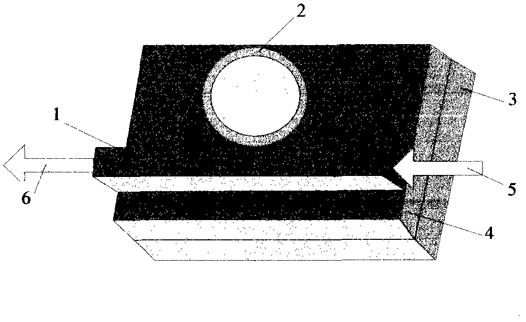
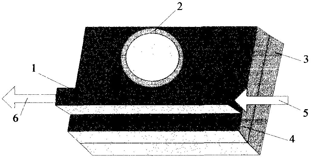
[0019] The key structural diagram of the all-optical logic gate based on the optical waveguide microring resonator in the present invention is as follows figure 1 shown. An all-optical logic device based on an optical waveguide microring resonator includes an optical waveguide 1 capable of transmitting signal light pulses and control light pulses, a nanoscale optical waveguide microring resonator 2, a substrate layer 3, a buffer layer 4, and optical The incident optical fiber 5 and the outgoing optical fiber 6 connected by the waveguide, wherein the optical waveguide micro-ring resonator 2 is located in the middle of the input end and the output end of the optical waveguide 1 . The laser light emitted by the light source is used as a...


PUM


Abstract

The invention provides an optical waveguide micro-ring resonant cavity-based all-optical logic gate, which comprises an optical waveguide (1), an optical waveguide micro-ring resonant cavity (2), a substrate (3), a buffer layer (4) as well as an incoming optical fiber (5) and an outgoing optical fiber (6), wherein the optical waveguide (1) is capable of inputting signal optical pulse and controlling optical pulse; the incoming optical fiber (5) and the outgoing optical fiber (6) are connected with the optical waveguide (1); and the optical waveguide micro-ring resonant cavity (2) is located in the middle position between an input end and an output end of the optical waveguide (1). The invention also discloses a method for realizing logic operation by utilizing the all-optical logic gate. The invention designs and provides an optical logic operation device, which is capable of executing optical logic operation, simple in structure, low in switch threshold value, low in power consumption, rapid in speed, wider in application range and capable of being realized on a semiconductor material substrate by using an integrated manufacturing process. Compared with the prior optical logic devices, the optical logic operation device of the invention is more convenient and practical and can be widely applied in all-optical computation, all-optical communication and integrated optical circuit systems.

Description

technical field [0001] The invention mainly relates to an optical logic gate operation device for realizing all-optical logic operations on light wave signals, which is applied in the fields of all-optical computing, all-optical communication, and integrated optical circuits, and especially relates to an all-optical logic gate operation device based on the nonlinear effect of a microring resonant cavity. A logic gate operation device and a logic operation method thereof. Background technique [0002] In high-speed optical communication networks, optical signal processing is an indispensable functional unit, and high-speed all-optical logic gates are the most basic functional components for optical signal processing, and are key core devices. Therefore, bandwidth requirements are becoming increasingly demanding today. How to realize higher-speed all-optical logic gates has become a hot spot in optical communication research. The all-optical logic gate uses photons in the wav...

Claims


Application Information

Patent Timeline
IPC IPC(8): G02F3/00G02B6/122
Inventor 薛晨阳朱平崔丹凤臧俊斌韦丽萍王永华晋玉剑仝小刚
Owner ZHONGBEI UNIV
Learn More