
Calibration method based on phase measurement of double-wavelength laser tube and distance measurement device of double-wavelength laser tube

A technology of phase measurement and calibration method, applied in the direction of measuring device, measuring distance, using optical device, etc., can solve the problems of inability to fully calibrate temperature phase, drift, etc., and achieve the effect of strengthening application, reducing performance requirements, and improving measurement accuracy

Active Publication Date: 2012-07-04
JIANGSU LAITZ MEASURING& CONTROL TECH CO LTD +1
View PDF5 Cites 31 Cited by
  • Summary
  • Abstract
  • Description
  • Claims
  • Application Information

AI Technical Summary

Problems solved by technology

[0015] The purpose of the embodiment of the present invention is to provide a calibration method for phase measurement. Based on the traditional dual-send-single-receive system, a dual-wavelength laser tube with different wavelengths and a light-emitting chip is used to solve the problem of dual-channel independent simultaneous laser tubes in the prior art. The wavelength laser tube cannot fully calibrate the phase drift caused by temperature

Method used


Image

  • Calibration method based on phase measurement of double-wavelength laser tube and distance measurement device of double-wavelength laser tube
  • Calibration method based on phase measurement of double-wavelength laser tube and distance measurement device of double-wavelength laser tube
  • Calibration method based on phase measurement of double-wavelength laser tube and distance measurement device of double-wavelength laser tube

Examples


Embodiment Construction

[0039] In order to make the object, technical solution and advantages of the present invention clearer, the present invention will be further described in detail below in conjunction with the accompanying drawings and embodiments. It should be understood that the specific embodiments described here are only used to explain the present invention, not to limit the present invention.

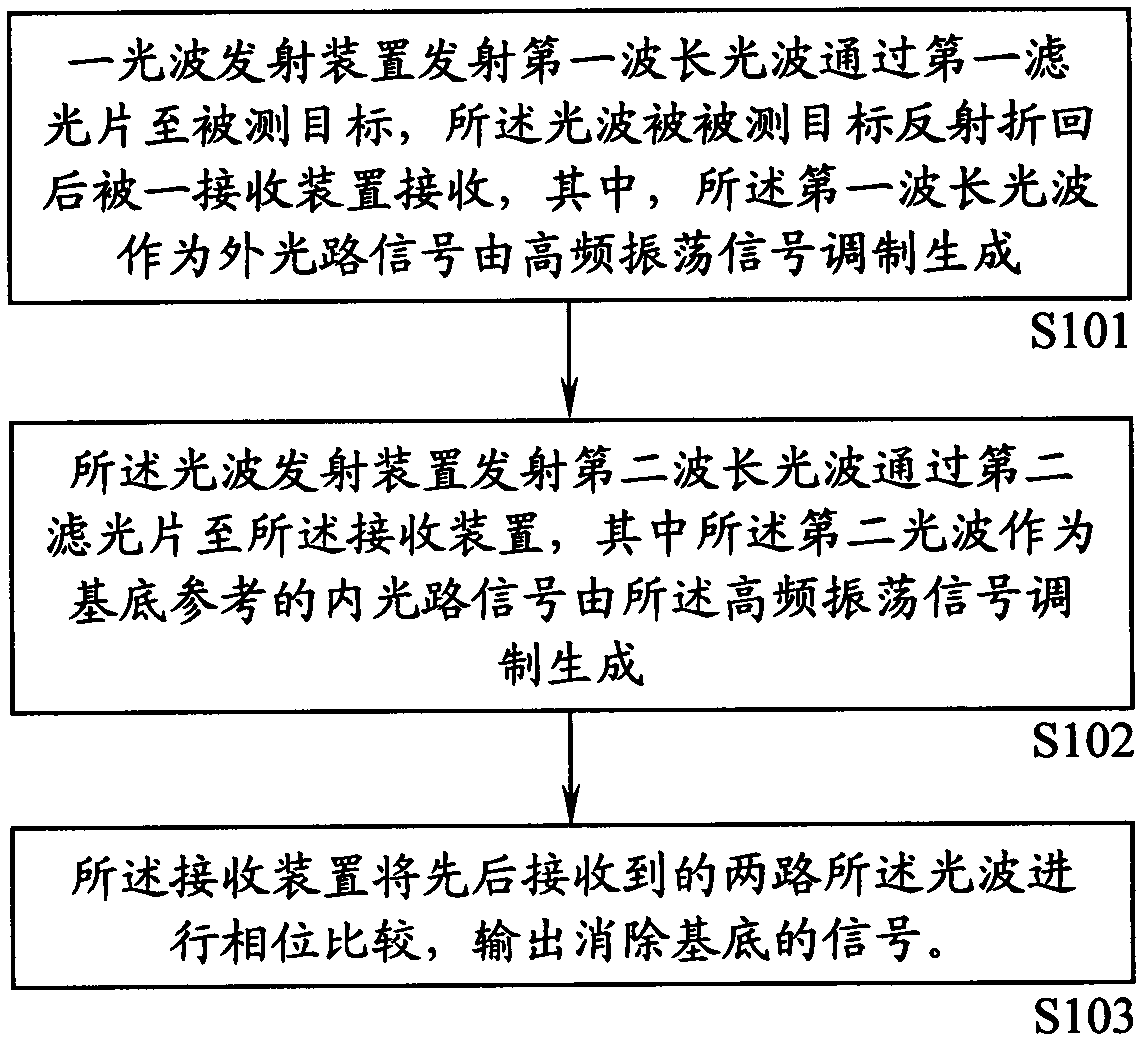
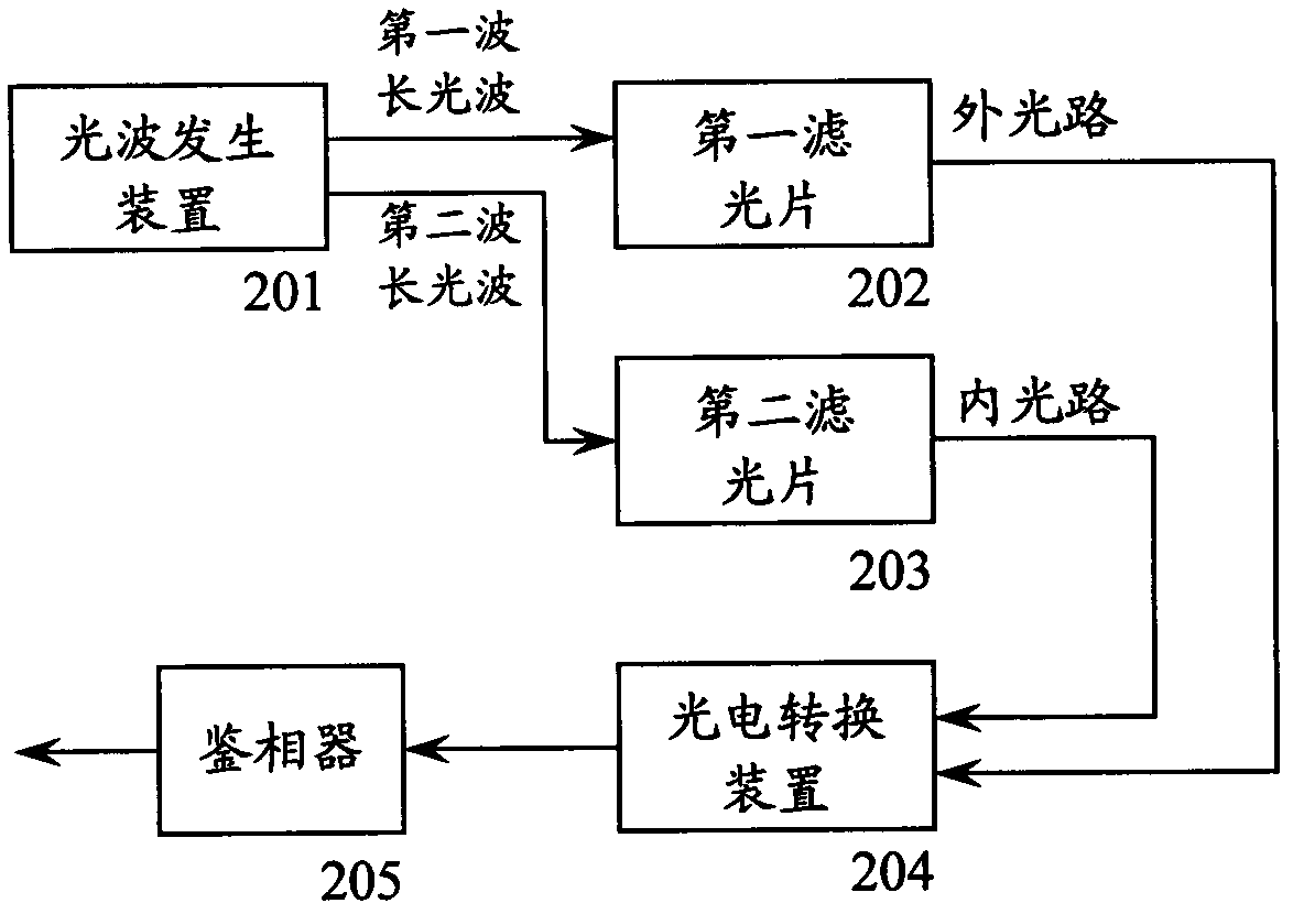
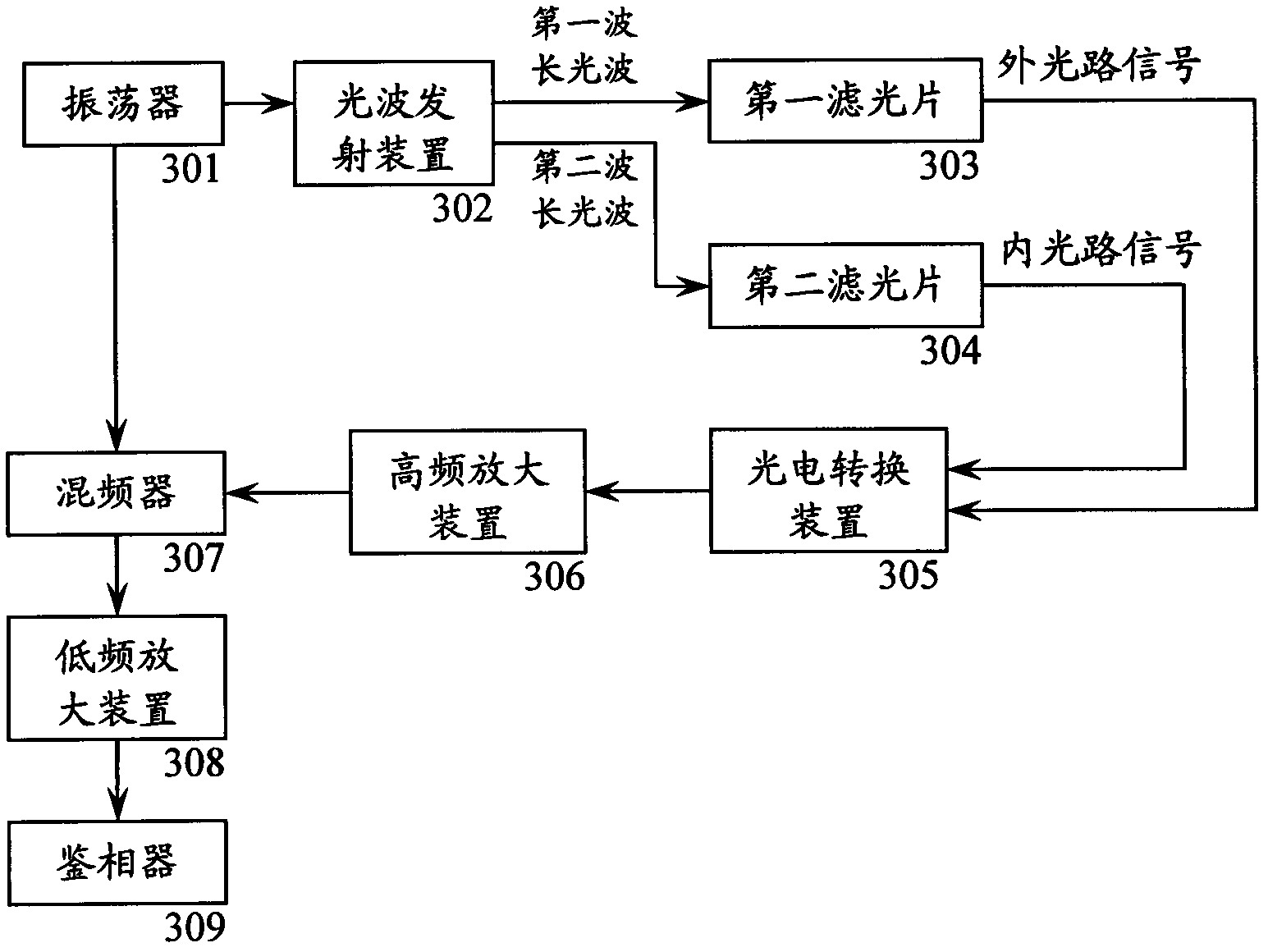
[0040]The embodiment of the present invention utilizes a dual-wavelength laser tube’s calibration method for phase measurement of dual-transmission and single-reception dual-optical paths, and adopts a light-wave transmitting device to successively emit two light waves with different wavelengths to pass through corresponding optical filters to generate internal and external optical-path signals respectively, and then Receive the return signals of the inner optical path signal and the outer optical path signal through a signal receiving device, and compare the phases of the return signals of the inne...


PUM


Abstract

The invention is applicable to the field of phase type photoelectric distance measurement and provides a calibration method based on phase measurement of a double-wavelength laser tube and a distance measurement device of the double-wavelength laser tube. The method comprises the following steps of: 1, forming an external light path; 2, forming an internal light path; and 3, sequentially switching a first light wave and a second light wave of light wave transmitting devices (1 and 2) during operation of the steps 1 and 2 to compare phases of the sequentially-received light waves of the internal and external light paths through a receiving device (7), and outputting a phase signal for eliminating a base reference. By the method, aims of phase compensation and calibration are fulfilled, uncertain phase noise which is introduced into a circuit due to environmental change is eliminated, the distance measurement accuracy of laser is improved, the influence of environmental factors on a distance measurement error is reduced, the cost of a system is reduced, and application of a phase type photoelectric distance measurement system in various industries is enhanced.

Description

technical field [0001] The invention belongs to the field of photoelectric distance measurement, and in particular relates to a calibration method and a distance measurement device based on dual-wavelength laser tube phase measurement. Background technique [0002] Laser has always been an invention that human beings are proud of. It has the characteristics of precision, speed, convenience, and strong anti-interference. The laser technology developed from this has solved many technical obstacles that traditional technologies cannot solve. The laser range finder, which is a combination of electronic technology, has received more and more attention from civil, military and industrial industries in the fields of length, height, distance, speed, and shape. It has been widely used in the following fields abroad: major industrial and mining enterprises , power petrochemical, water conservancy, communication, environment, construction, geology, police, fire protection, blasting, na...

Claims


Application Information

Patent Timeline
Patent Type & Authority Applications(China)
IPC IPC(8): G01S7/497G01S17/08G01J9/00G01S7/4911
CPCG01C3/00H01S5/00G01C25/00G01S7/497G01S17/36G01C3/08G01S7/4911G01B11/14
Inventor 杜鑫乔佰文查晓怡
Owner JIANGSU LAITZ MEASURING& CONTROL TECH CO LTD
Learn More