Testing device for alternating-current relays and testing method thereof
An AC relay and testing device technology, applied in circuit breaker testing and other directions, can solve the problems of low inspection efficiency, long time consumption, poor accuracy, etc., and achieve the effects of improving work efficiency, low production cost, and high accuracy
- Summary
- Abstract
- Description
- Claims
- Application Information
AI Technical Summary
Problems solved by technology
Method used
Image
Examples
Embodiment approach
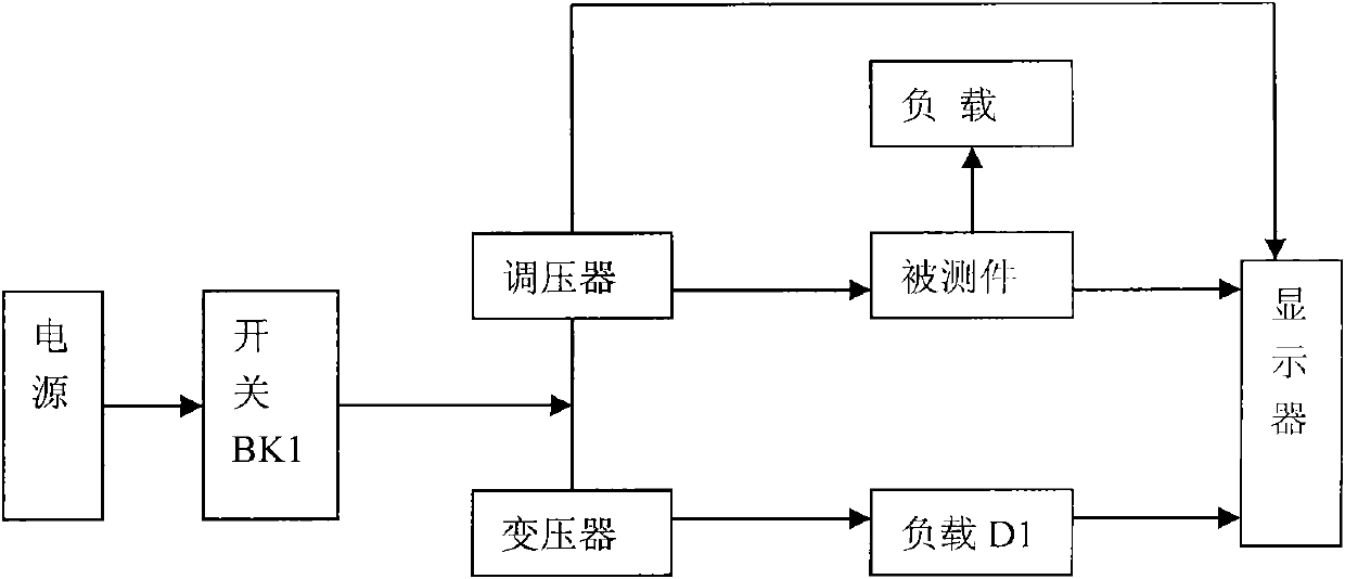
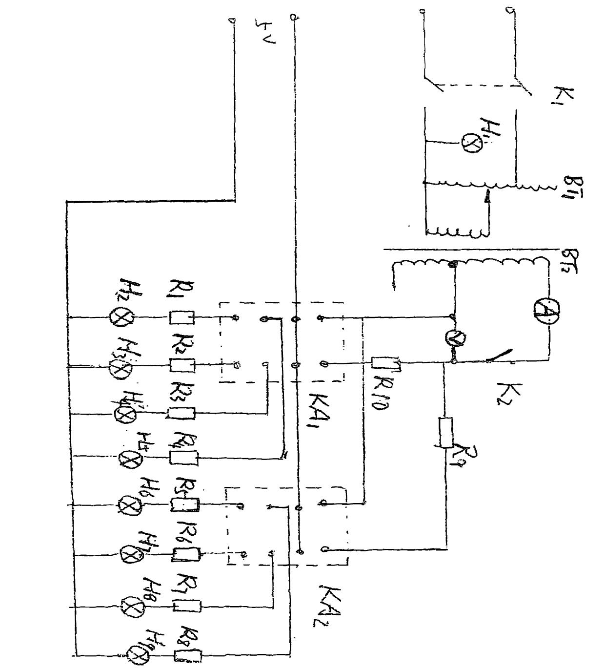
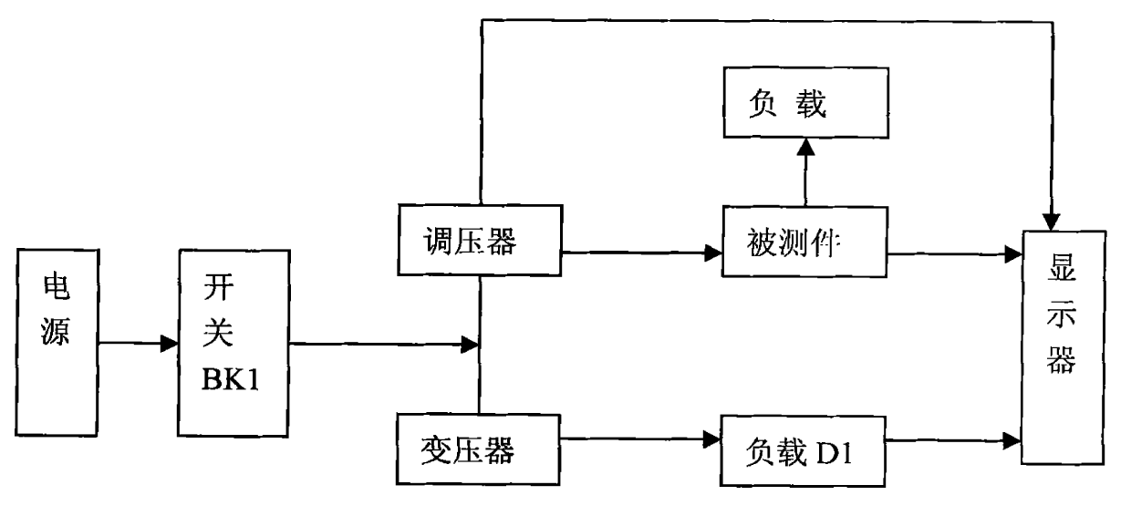
[0014] Embodiments of the present invention refer to figure 1 : The test device circuit of the AC relay is composed of the following parts: power switch KA1, KA2, fuse FU1, FU2, transformer, power indicator, voltage regulator BT1, transformer BT2, ammeter A1, voltmeter V1, display indicator HL1 , HL2, HL3, resistors R1-R10, relay sockets KA1-KA2, shock absorbers. 220V AC power is introduced from the primary side of the transformer, and the secondary side of the transformer outputs two sets of AC power, 220V and 6.3V, to provide working power for circuits and indicator lights. The 6.3V indicator light used to indicate the circuit state and the indicator light D1-D4 indicating the working state of the AC contactor, and the current limiting resistor R1-R4, the resistance value of which is 62-10W, where D1-D4 is 220, 200W red, green, Colored light bulbs. One end of the 0-220V voltage regulator B1 is connected to 220, the other end is connected to the AC contactor line package, t...
PUM
 Abstract
Description
Claims
Application Information
 - R&D
- Intellectual Property
- Life Sciences
- Materials
- Tech Scout
- Unparalleled Data Quality
- Higher Quality Content
- 60% Fewer Hallucinations
Browse by: Latest US Patents, China's latest patents, Technical Efficacy Thesaurus, Application Domain, Technology Topic, Popular Technical Reports.
© 2025 PatSnap. All rights reserved.Legal|Privacy policy|Modern Slavery Act Transparency Statement|Sitemap|About US| Contact US: help@patsnap.com


