
Verticality adjusting method

An adjustment method and verticality technology, applied in the field of measurement, can solve the problems of mirror coating damage, inability to obtain measurement accuracy, etc., and achieve the effects of easy acquisition, simple and convenient operation, and high precision

Inactive Publication Date: 2012-07-04
CRRC DALIAN CO LTD
View PDF4 Cites 13 Cited by
  • Summary
  • Abstract
  • Description
  • Claims
  • Application Information

AI Technical Summary

Problems solved by technology

At present, the more common verticality measurement and adjustment method is to use a high-precision square to directly measure and adjust the verticality of the optical bridge and the mirror surface on the measurement platform. This method of visual estimation using the light gap method cannot obtain high measurement The accuracy can only reach 10" after the experiment adjustment, and in the process of measurement and adjustment, the square body needs to repeatedly touch the mirror surface, which is very easy to damage the mirror coating

Method used


Image

  • Verticality adjusting method
  • Verticality adjusting method
  • Verticality adjusting method

Examples


Embodiment Construction

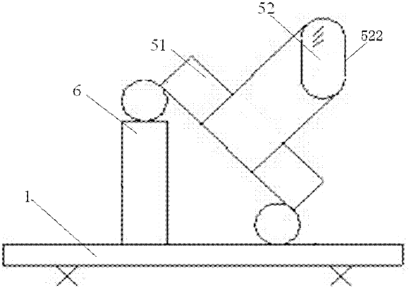
[0016] Embodiment 1 of the verticality adjustment method provided by the present invention can adopt such as figure 1 The verticality adjustment device shown is realized. The device includes a reference platform 1 , an optical autocollimator 4 , a support 3 and a standard gauge block 2 . A support 3 and the optical autocollimator 4 are placed on the reference platform 1, a fixing clip is provided on the support 3, and the standard gauge block 2 can be clamped on the support 3 by a fixing clip; The above-mentioned optical autocollimator 4 can be adjusted in height through spacers. This embodiment includes the following steps:

[0017] Step 1, adjust the height of the optical autocollimator 4 placed on the reference platform 1, so that the optical axis of the optical autocollimator 4 is basically the same as the height of the center line of the part to be adjusted in the tested part from the reference platform 1, Such as figure 1 shown. The height of the optical autocollima...


PUM


Abstract

The invention provides a verticality adjusting method. The verticality adjusting method comprises the steps of: performing verticality zero-position reference determination on an optical autocollimator by using a standard gauge block firstly; and then, adjusting one of two parts required to be vertical to each other in measured parts based on the verticality zero-position reference. According to the verticality adjusting method, the adopted measuring tools are all common instruments and measuring tools and are easily obtained, the whole method is simple and convenient to operate, and the adjustment and test result accuracy is high, so that the verticality adjusting method can be widely applied to the adjustment of accessory manufacture of similar detection devices and measurement instruments.

Description

technical field [0001] The invention relates to measurement technology, in particular to a verticality adjustment method. Background technique [0002] The hole systems of crankshaft holes and camshaft holes on various diesel engine bodies need to measure the coaxiality error of the hole system according to the requirements of the drawings. At present, the measurement of the coaxiality error of the hole system usually uses an optical measuring bridge and a reflecting mirror perpendicular to the optical measuring bridge. Among them, the verticality requirements between the mirror surface and the optical measuring bridge are relatively high, and the verticality error cannot be greater than 3″. At present, the more common verticality measurement and adjustment method is to use a high-precision square to directly measure the optical measuring bridge and the reflection on the measuring platform. The verticality of the mirror surface is measured and adjusted. This method of visua...

Claims


Application Information

Patent Timeline
Patent Type & Authority Applications(China)
IPC IPC(8): G01B11/26
Inventor 钱巍钱菘栾俏梅
Owner CRRC DALIAN CO LTD
Learn More