
Rotational flow and direct current combined gas burner

A gas burner and gas fuel technology, applied in the direction of gas fuel burners, burners, combustion methods, etc., can solve the problem of air volume variation of the lower pulverized coal burner, over-temperature of the panel heating surface, short gas fuel burnout distance, etc. problems, to achieve the effect of avoiding energy waste and environmental pollution, low NOx emissions, and good social benefits

Active Publication Date: 2014-08-27
DONGFANG BOILER GROUP OF DONGFANG ELECTRIC CORP
View PDF5 Cites 0 Cited by
  • Summary
  • Abstract
  • Description
  • Claims
  • Application Information

AI Technical Summary

Problems solved by technology

If the gas burner is arranged separately above the burnout air, the burnout distance of the gas fuel will be too short, which will affect the burnout of the gas fuel and may cause overheating of the panel heating surface; in addition, the separate air distribution of the gas burner will cause The air volume of the lower pulverized coal burner changes, which affects the normal operation of the pulverized coal burner
[0004] In addition, when gaseous fuel is used, due to the large amount of gas and the exhaust air volume can only meet the complete combustion of part of the gaseous fuel, it is difficult to ensure the uniform mixing of fuel and air before entering the furnace with the traditional structure, which will definitely affect the gaseous fuel. Timely ignition and good burnout

Method used


Image

  • Rotational flow and direct current combined gas burner
  • Rotational flow and direct current combined gas burner
  • Rotational flow and direct current combined gas burner

Examples


Embodiment Construction

[0025] The following non-limiting examples illustrate the invention.

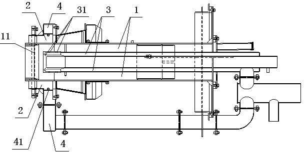
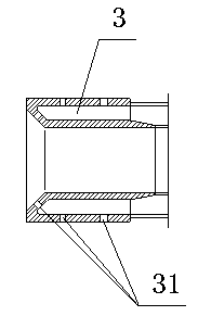
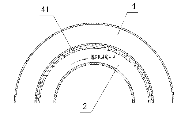
[0026] Such as Figures 1 to 3 As shown, a gas burner of a combination of swirling flow and direct flow includes an overfired air passage through which the overfired air passes and a gas passage through which gas fuel is passed through. The overfired air passage includes a central direct flow air passage 1 and a The outlet 11 of the swirling air passage 2 and the direct-flow air passage 1 is a shrinking type. The gas channel includes a central air intake channel 3 located in the direct air channel 1, the gas fuel sprayed from the front end gas nozzle 31 is mixed with the direct air in the direct air channel 1, and the middle cavity of the central air intake channel 3 is used to place the igniter And the monitoring device, also includes the circumferential air intake channel 4 that is located at the periphery of the swirling wind channel 2, and the gas fuel sprayed from the front end gas nozzle 41 is mixed ...


PUM


Abstract

The invention discloses a rotational flow and direct current combined gas burner, and belongs to the field of gas burners. The gas burner comprises a burnout air channel with burnout air and a gas channel with a gas fuel, wherein the burnout air channel comprises a central direct current air channel and a peripheral rotational flow air channel; the gas channel comprises a central air inlet channel in the direct current air channel, and a gas nozzle at the front end of the gas channel spouts the gas fuel so as to be mixed with the direct current air in the direct current air channel; and the gas burner also comprises a circumferential inlet channel arranged on the periphery of the rotational flow air channel, and the gas nozzle at the front end of the gas burner spouts the gas fuel so as to be mixed with the rotational flow air in the rotational flow air channel. The gas burner provided by the invention can be used for reducing the adulterate burning difficulty of a high-heating-value gas fuel, when the gas fuel is put into operation, the good commixture and combustion of the gas fuel and air are ensured; and when the gas fuel is off stream, the burnout air function is still completely realized, and the burnout of coat dust and low NOx discharge capacity of the boiler are guaranteed.

Description

technical field [0001] The invention belongs to a gas burner, in particular to a gas burner used in a pulverized coal boiler whose front and rear walls oppose each other. Background technique [0002] When the gas fuel is used as a blended fuel in a coal-fired boiler, if the fuel consumption is large and long-term operation is required, a special gas burner must be installed. Gas fuel is generally divided into two types: high calorific value gas fuel and low calorific value gas fuel, and the gas burner is also designed according to the type of gas fuel. When a large amount of gas fuel is blended in a pulverized coal boiler, the gas fuel with high calorific value is generally fed into the furnace from a suitable position above the pulverized coal burner or the upper part of the pulverized coal burner; The lower part or the lower part of the pulverized coal burner is sent into the furnace at a suitable position. Most of the current large-scale power plant boilers are of the ...

Claims


Application Information

Patent Timeline
Patent Type & Authority Patents(China)
IPC IPC(8): F23D14/02F23D14/46F23D14/64
Inventor 但家瑜
Owner DONGFANG BOILER GROUP OF DONGFANG ELECTRIC CORP
Learn More