
Fully hydraulically driven multi-stirring wheel synchronization device for stirring curer

A technology of synchronous device and curing machine, which is applied in the direction of soil protection, excavation, sheet pile wall, etc., which can solve the problems that the speed synchronization cannot be guaranteed, achieve the effect of speed synchronization and improve work efficiency

Inactive Publication Date: 2014-06-18
龙工(上海)机械制造有限公司 +1
View PDF5 Cites 0 Cited by
  • Summary
  • Abstract
  • Description
  • Claims
  • Application Information

AI Technical Summary

Problems solved by technology

[0003] At present, the stirring wheels on the stirring curing machine cannot guarantee the speed synchronization due to the influence of different stirring resistance.

Method used


Image

  • Fully hydraulically driven multi-stirring wheel synchronization device for stirring curer
  • Fully hydraulically driven multi-stirring wheel synchronization device for stirring curer
  • Fully hydraulically driven multi-stirring wheel synchronization device for stirring curer

Examples


Embodiment 1

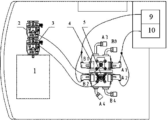
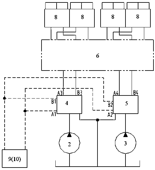
[0016] Such as figure 1 and figure 2 As shown, the multi-wheel synchronizing device of the agitating wheel of a fully hydraulically driven stirring and curing machine provided in this embodiment includes a first hydraulic pump 2 and a second hydraulic pump 3, and the first hydraulic pump 2 and the second hydraulic pump 3 are driven by the engine. 1 provides power and is installed on the chassis together with engine 1. The first main valve 4 and the second main valve 5 are installed on the chassis. The first handle 9 and the second handle 10 are fixed in the cab.

[0017] The first hydraulic pump 2 is connected to the first main valve 4 through a hose and a joint, and the second hydraulic pump 3 is connected to the second main valve 5 through a hose and a joint. The dual pumps provide a maximum working flow of 220L / min×2 and a maximum working pressure of 32MPa High-pressure hydraulic oil is referred to as high-pressure oil. The main oil port A3 and the main oil port B3 in ...

Embodiment 2

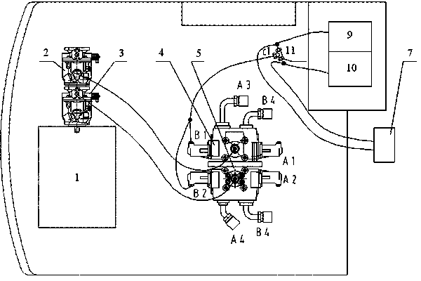
[0021] Such as image 3 and Figure 4 As shown, the difference between this embodiment and Embodiment 1 is that the first handle oil port 9 and the second handle oil port 10 are connected to the diverter valve 7 through the shuttle valve 11 . The pilot pressure port c1 of the shuttle valve 11 is respectively connected in series with the pilot oil port B1 of the first main valve 4 and the pilot oil port B2 of the second main valve 5 through a hose and a joint. The main oil port A3 of the first main valve 4 (the main oil port A4 of the second main valve 5 is connected to the oil inlet of the diverter valve 7 through the rubber hose, and the oil outlet of the diverter valve 7 is respectively connected to the four stirring wheels through the rubber hose and joints .

[0022] The low-pressure pilot oil from the first handle oil port 9 and the second handle oil port 10 obtains a relatively high pressure through the shuttle valve 7, and the low-pressure pilot control oil is...


PUM


Abstract

The invention provides a fully hydraulically driven multi-stirring wheel synchronization device for stirring curer. The device comprises a first and a second hydraulic pumps driven by the engine of a stirring curer and connected with each other, the first and the second hydraulic pumps are connected with a first main valve and a second main valve respectively, main oil ports of the first and the second main valves are connected with a flow dividing / combining valve or flow dividing valve, the oil outlet of the flow dividing / combining valve or flow dividing valve is connected with all stirring wheels of the stirring curer, handle oil ports are connected with the pilot oil ports of the first and second main valves or connected with the flow dividing valve via a shuttle valve, and the shuttle valve is connected with the pilot oil ports of the first and second main valves. The invention simultaneously drives the four stirring wheels on a stirring head via the flow dividing / combining valve or flow dividing valve, so as to ensure synchronous rotation speeds of all the stirring wheels, regardless of different stirring resistances, so that the stirring head can easily move downward in case of compact soil mass and can improve working efficiency in case of soft soil mass.

Description

technical field [0001] The invention relates to a multi-wheel synchronizing device for stirring wheels on a stirring and curing machine, belonging to the technical field of foundation stabilization machinery. Background technique [0002] Stirring and curing machine is a new type of foundation stabilization machine, and it is a pile construction machine widely used in foundation reinforcement and soil improvement projects such as beaches, airports, parking lots, rivers, lakes, and road slope stabilization. It is mainly used to stabilize the weak and loose soil layer, so that the improved soil layer reaches a certain hardness, and then carry out follow-up construction such as laying roads and building houses. It can also isolate polluted soil and neutralize toxic and harmful substances. waste, etc. It is also possible to excavate pipeline ditches and ditches in hard strata and construct underwater anti-seepage protective layers by changing different auxiliary working devices...

Claims


Application Information

Patent Timeline
Patent Type & Authority Patents(China)
IPC IPC(8): E02D3/12E02D17/20E02D5/46E02D5/18
Inventor 边永强曹秀君罗东升毛伟鹏邢宇兵
Owner 龙工(上海)机械制造有限公司
Learn More