
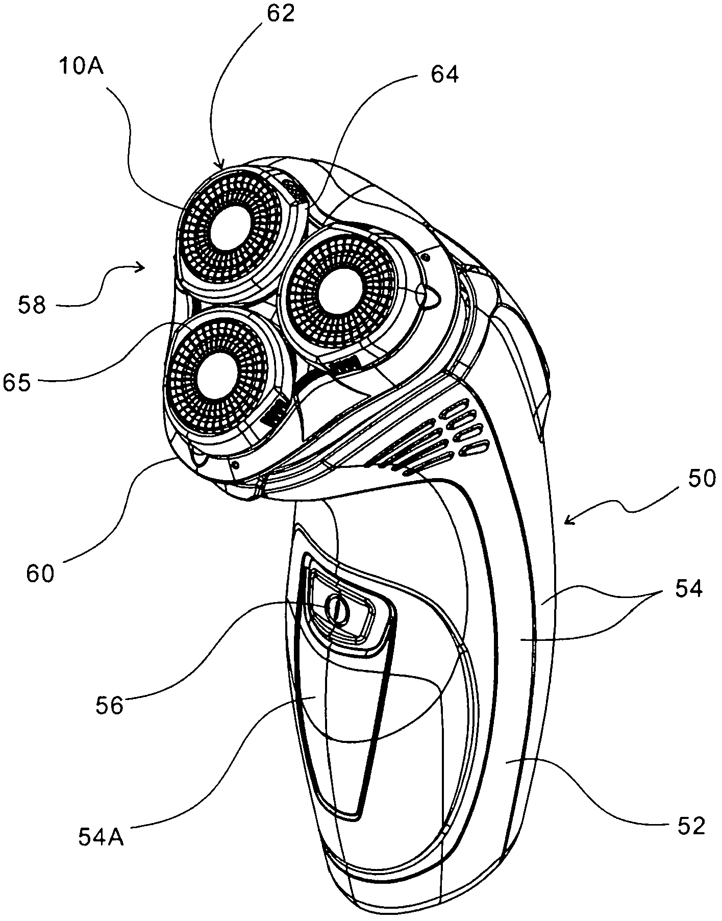
Rotary electric shaver and manufacturing method of outer cutter and inner cutter of the same

A rotary, cutter technology, applied in other manufacturing equipment/tools, manufacturing tools, metal processing, etc., can solve the problems of decreased productivity, deterioration of processing efficiency, complex processing, etc., to achieve easy assembly, good efficiency, and increased shaving area Effect

Inactive Publication Date: 2012-07-04
IZUMI PROD CO
View PDF18 Cites 5 Cited by
  • Summary
  • Abstract
  • Description
  • Claims
  • Application Information

AI Technical Summary

Problems solved by technology

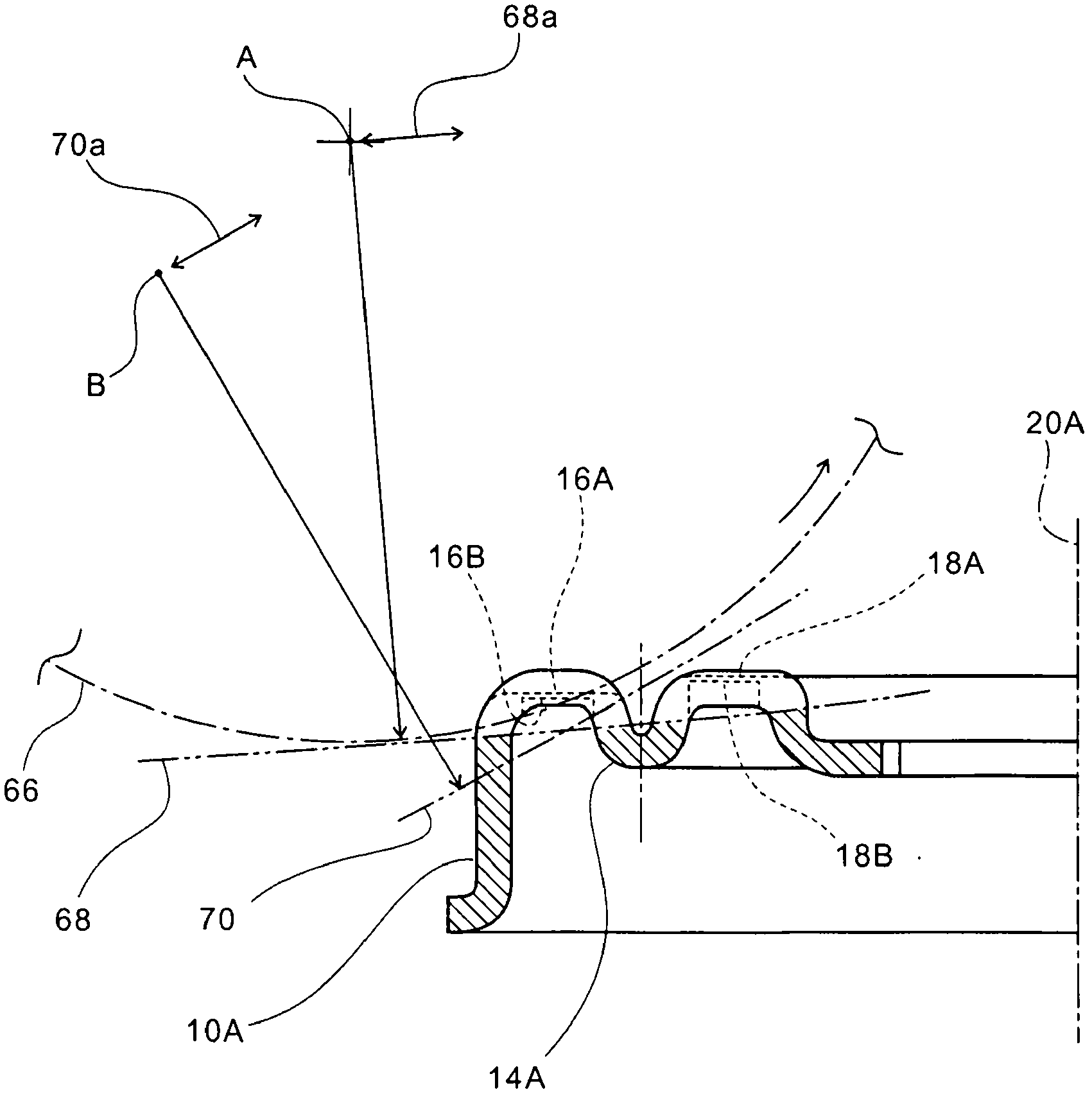
However, in this case, the processing of the upper surface of the outer cutter 10a, that is, the processing of the double annular shaving surfaces 16a, 18a becomes complicated. For this, it is necessary to make the small cutters 22a, 24a formed on the inner cutter 12a The tip (upper edge) of the knife is curved
Therefore, the processing efficiency of these deteriorates, and there is a problem that productivity falls
[0006] In the technology represented by JP2008-517696 (A) (corresponding to: US2009-025227A1, WO2006 / 048799), a triple concentric shaving surface is formed on the outer cutter, so that the shaving area is larger than the above-mentioned Image 6 Shown is more enlarged, but since the triple shaving face is located on a common plane, there is a Image 6 Same problem with the technique shown (see figure 1 and paragraph 0018 (corresponding to paragraph 0021 of US2009-025227A1))

Method used


Image

  • Rotary electric shaver and manufacturing method of outer cutter and inner cutter of the same
  • Rotary electric shaver and manufacturing method of outer cutter and inner cutter of the same
  • Rotary electric shaver and manufacturing method of outer cutter and inner cutter of the same

Examples


Embodiment Construction

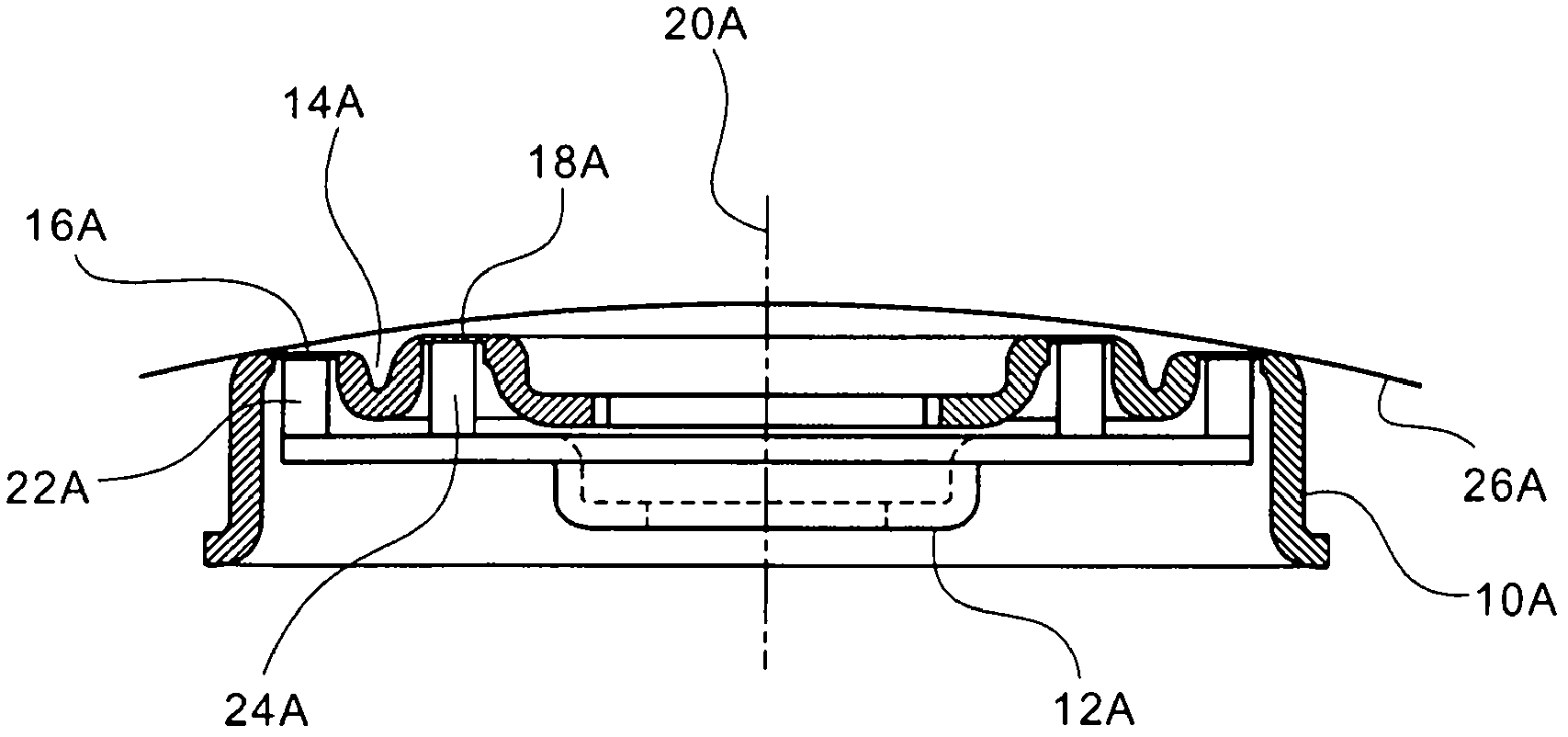
[0025] The annular shaving surface formed on the outer cutter may be a double concentric circle or a triple concentric circle. The beard entrance formed on the shaving surface of the outer cutter may be in the shape of a slit. If it is in the shape of a slit, when performing the machining of the outer tool described later, the rotating disc grinding wheel rotating around the horizontal axis can be moved toward its radial direction or the rotating disc grinding wheel can be slightly tilted towards its radial direction. The entire circular shaving surface is processed efficiently in one process.

[0026] On the inner cutter, it is possible to cut off (punching up (Japanese: 切りこし)) on a common metal plate, and integrally form a plurality of small cutters corresponding to all annular shaving surfaces with different radii of rotation, In this case, the structure of the inner cutter is also simplified. At this time, the center of rotation moves up and down (in a direction parallel...


PUM


Abstract

A rotary electric shaver includes an outer cutter which has an upper surface with annular shaving sections, in which many hair entry apertures are formed, and an inner cutter having small blades, which rotate in sliding contact with the outer cutter from below the shaving sections. The outer cutter (10A) has a plurality of concentric annular shaving sections (16A, 18A), which are integrally formed therewith. The shaving section (16A) adjacent to an outer periphery is lower than the shaving section (18A) adjacent to a center, the shaving sections being formed on a plane horizontal to a central axis (20A). This makes it possible to increase a shaving area, to precisely trace the curved surface of a concave portion of skin and to come in contact with the skin with a proper contact pressure, thus permitting smooth shaving of the concave portion. The shaver has a simple structure with a smaller number of components, featuring easier assembly and easier removal of hair bits.

Description

technical field [0001] The present invention relates to a rotary electric razor, and more particularly to a rotary electric razor having an outer cutter having an annular shaving face formed with a plurality of beard inlets, and an inner cutter having a A small cutter that rotates while the lower part of the surface is in sliding contact with the above-mentioned outer cutter. Furthermore, it relates to the manufacturing method of the outer cutter and inner cutter used for this rotary electric shaver. Background technique [0002] Such a rotary electric razor requires a substantially disk-shaped outer cutter to follow the fine unevenness of the skin delicately, and shave smoothly without shaving residue. For example, there is a problem of increased beard shaving residue in areas where there are large unevenness or skin folds, such as the lower side of the user's jaw. What take in prior art is to enlarge the area of ​​shaving face. [0003] Image 6 It shows the technique o...

Claims


Application Information

Patent Timeline
Patent Type & Authority Applications(China)
IPC IPC(8): B26B19/14B24B3/48
CPCB26B19/143Y10T29/49Y10T29/496
Inventor 三村良幸
Owner IZUMI PROD CO
Learn More