Safe self-destroying syringe

A self-destructing syringe technology, applied in the field of medical devices, can solve the problems of affecting tightness, no adjustment space, high injection cost, etc., and achieve the effect of preventing abnormal displacement, avoiding repeated use, and reasonable structural design

Inactive Publication Date: 2015-05-27
伊森医药科技(上海)有限公司
View PDF4 Cites 0 Cited by
  • Summary
  • Abstract
  • Description
  • Claims
  • Application Information

AI Technical Summary

Problems solved by technology

However, for the syringe of this structure, since the annular protruding ring and the annular groove are provided with inclined slopes, some syringes have their needle seats entered into the syringe when they are not in use or mishandled, which affects the use of the syringe and causes the syringe to be damaged. Scrap, which in turn leads to high injection costs
[0003] For this reason, people design a groove inside the injection barrel, and then use the convex ring design of the needle seat to directly engage to achieve the effect. However, the friction force between the convex ring of the needle seat and the groove of the cylinder body is very vulnerable to temperature changes. And affect its tightness, it may be looser or tighter, often causing confusion for medical staff, and more seriously, it may cause unpredictable injuries
Another commonly used design is to add an expansion ring to the elastic card body of the needle seat, and use the expansion ring to support the large elastic body into the groove to achieve the purpose of limiting movement. However, due to time and physical factors, it is more difficult to protect the material. Unfavorable response caused by elastic fatigue
The most important thing is that the design of the grooves in these two barrels has already limited their engagement force, and there is not enough room for adjustment.
Moreover, this kind of syringe has a groove on the inner side of the syringe, which is really difficult to process, especially its angle, size, and size will be limited due to demoulding.

Method used


Image

  • Safe self-destroying syringe
  • Safe self-destroying syringe
  • Safe self-destroying syringe

Examples


Embodiment 1

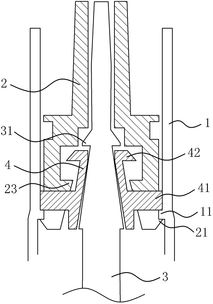
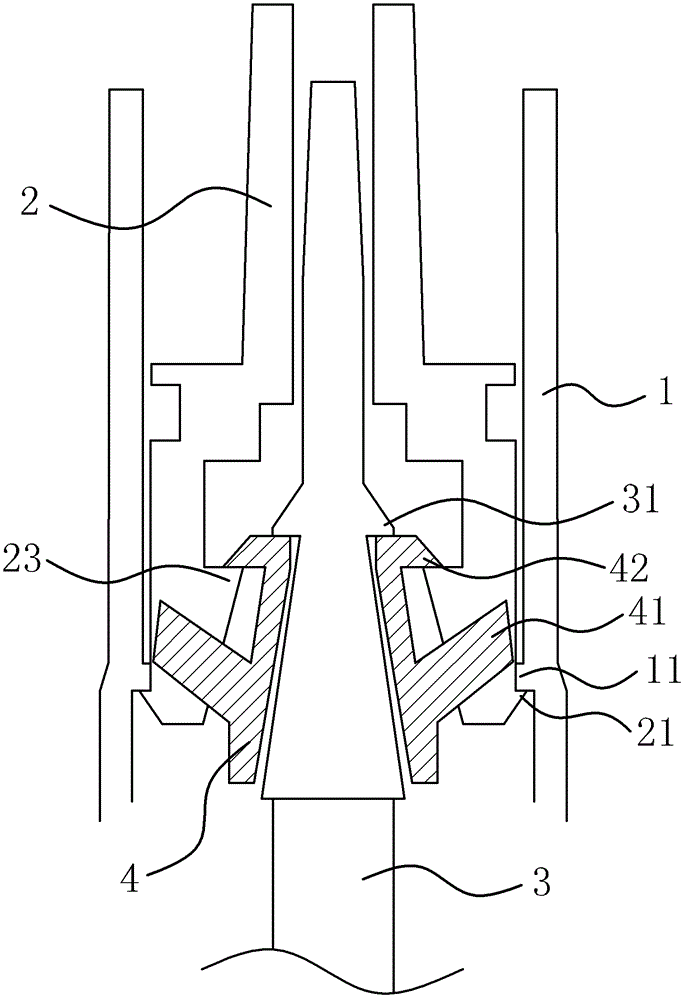
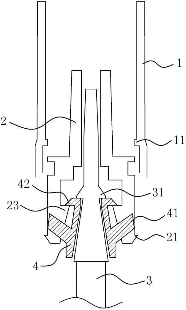
[0035] Such as figure 1 , figure 2 and image 3 The safety self-destructing syringe shown mainly includes a syringe 1, a needle seat 2 sealed inside the front end of the syringe 1 and a needle bar 3 inside the syringe 1, the front end of the needle bar 3 can be inserted into into the needle seat 2. Such as Figure 1-4 As shown, the inner side of the front end of the syringe 1 is provided with an annular step 11 capable of limiting the needle base 2 , and the needle base 2 has a limiting boss 21 which can abut against the inner surface of the annular step 11 .

[0036] Such as Figure 5 As shown, the needle holder 2 is located at one end of the limiting boss 21 and is provided with a plurality of locking grooves 22 along its axial direction. Such as figure 1 , figure 2 and image 3 As shown, the needle bar 3 is sleeved with a cylindrical elastic limiter 4, the side of the elastic limiter 4 has a number of elastic limiters 41 corresponding to the slot 22, the elastic l...

Embodiment 2

[0046] The structural principle of this embodiment is basically the same as that of Embodiment 1, the difference is that: Figure 8 and Figure 9 As shown, there are two elastic limiting parts 41 , the elastic limiting parts 41 are arranged symmetrically, and there are also two locking slots 22 , and the two elastic limiting parts 41 are respectively located in the locking slots 22 .


PUM


Abstract

The invention provides a safe self-destroying syringe and belongs to the technical field of machinery. The problems of complex structure and difficulty in processing of the present self-destroying syringe are solved. The safe self-destroying syringe comprises a needle cylinder, a needle head base and a needle bar, wherein an annular stair is arranged at the inner side of the front end of the needle cylinder; a limiting boss is arranged on the needle head base; an one-way structure is arranged between the needle head base and the needle bar; a plurality of slots are arranged on the needle head base; an elastic limiting piece is sleeved on the needle bar; elastic limiting parts which are correspondingly arranged with the slots are arranged on a lateral part of the elastic limiting piece; the elastic limiting parts are outward bulged along radial direction and can axially move in the slots; and when the limiting boss crosses the annular stair and is resisted against the inner side wall of the annular stair, one sides of the elastic limiting parts are resisted against the bottoms of the slots while the other sides are resisted against the outer side wall of the annular stair. The safe self-destroying syringe has the advantages of reasonable structure, excellent self-destroying effect, and the like.

Description

technical field [0001] The invention belongs to the technical field of medical devices, and relates to a syringe, in particular to a safe self-destruction syringe. Background technique [0002] In order to avoid virus cross-infection caused by using unhygienic syringes, disposable syringes have been widely used in the medical field. When the existing disposable syringes are in use, in order to achieve the purpose of self-destruct, a clamping structure is provided between the needle base and the injection cylinder to facilitate the needle base to be pulled back into the syringe, and the clamping structure can also prevent the needle base from Move the syringe forward to prevent it from falling out. This clamping structure includes an annular groove arranged inside the syringe and an annular protruding ring arranged on the needle seat. The side of the annular protruding ring located on the injection rod is an inclined slope, and the annular groove corresponds to the inclined ...

Claims


Application Information

Patent Timeline
Patent Type & Authority Patents(China)
IPC IPC(8): A61M5/50A61M5/178
Inventor 徐雪花
Owner 伊森医药科技(上海)有限公司
Why Eureka
Try Eureka