Subtraction elastography method

An imaging method and image subtraction technology, applied in the directions of ultrasound/sonic/infrasonic image/data processing, ultrasound/sonic/infrasonic Permian technology, organ movement/change detection, etc. problem, to achieve the effect of reliable damage boundary information, high signal-to-noise ratio, and improved imaging quality

Inactive Publication Date: 2012-07-04
BEIJING SONICEXPERT MEDICAL TECH CO LTD +1
View PDF3 Cites 6 Cited by
  • Summary
  • Abstract
  • Description
  • Claims
  • Application Information

AI Technical Summary

Problems solved by technology

[0009] Although elastography is widely studied and subtraction technology is widely used in medical imaging, there is no systematic research on the use of subtraction technology for elastography and the combination of elastography and subtraction technology. to report

Method used


Image

  • Subtraction elastography method
  • Subtraction elastography method
  • Subtraction elastography method

Examples


Embodiment 1

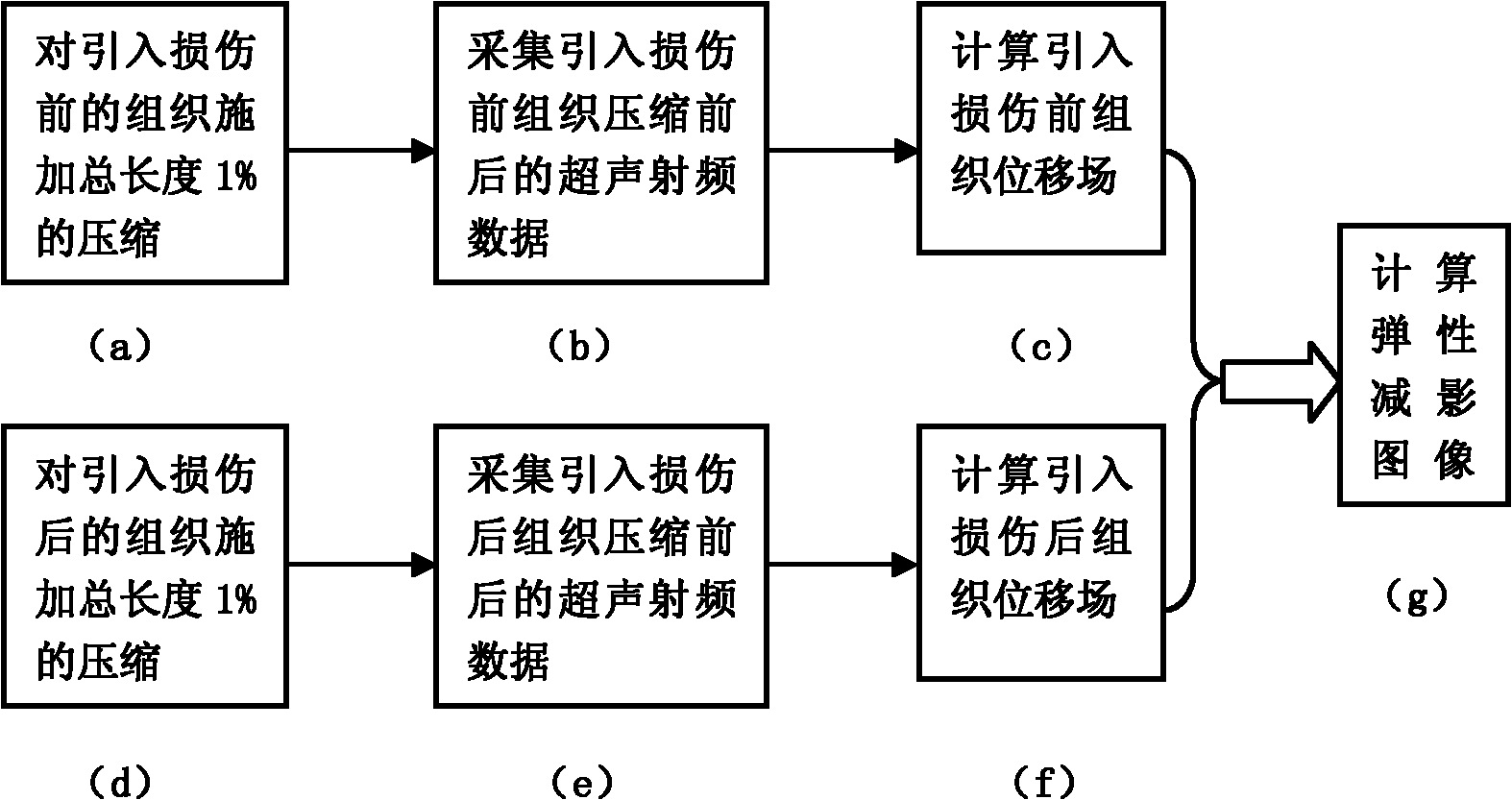
[0030] Embodiment 1 is an embodiment of elastic subtraction imaging based on strain field, which embodiment includes the following steps:

[0031] 1) Apply a certain amount of compression to the tissue before the damage is introduced, and collect ultrasonic radio frequency data before and after compression. The specific steps are as follows: first, according to figure 1 As shown in (a), a compression of 1% of the total length is applied longitudinally to the tissue before the injury is introduced, and according to figure 1 (b) shows the ultrasound RF data acquired before and after compression. Assume that the collected ultrasonic radio frequency data includes N scan lines, each scan line includes L point data, and the actual distance corresponding to two adjacent point data is Δz.

[0032] 2) Apply certain compression to the tissue after the damage is introduced, and collect ultrasonic radio frequency data before and after compression. The specific steps are as follows: figu...

Embodiment 2

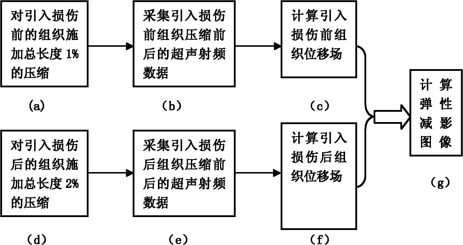
[0060] Embodiment 2 is an embodiment of elastic subtraction imaging based on a regularized displacement field. The elastic subtraction imaging based on a regularized displacement field can deal with the situation that the amount of compression suffered by the tissue before and after the injury is inconsistent. By regularizing the displacement field, even if the amount of tissue compression is different before and after the damage is introduced, better elastic subtraction imaging results can be obtained. This embodiment includes the following steps:

[0061] 1) Apply certain compression to the tissue before the damage is introduced, and collect ultrasonic radio frequency data before and after compression, the specific steps are as follows: figure 2 As shown in (a), a compression of 1% of the total length is applied longitudinally to the tissue before the injury is introduced, and as figure 2 (b) shows ultrasonic radio frequency data collected before and after compression, ass...


PUM


Abstract

The invention relates to a subtraction elastography method, and belongs to the technical field of ultrasonic subtraction elastography. The method comprises the following steps of: carrying out certain compression on a tissue before injury is introduced, and collecting ultrasonic radio frequency data before and after compression; carrying out certain compression to the tissue after injury is introduced, and collecting ultrasonic radio frequency data before and after compression; calculating a displacement field of the tissue before injury is introduced according to the collected ultrasonic radio frequency data; calculating a displacement field of the tissue after injury is introduced according to the collected ultrasonic radio frequency data; and calculating a subtraction elastography image according to the results obtained in the two steps. The subtraction elastography method combines an elastography technology and a subtraction angiography technology, and can highlight differences in an elastography image, and inhibit the same background structure at the same time. Meanwhile, the invention provides an embodiment of strain field-based subtraction elastography and an embodiment of regular displacement field-based subtraction elastography. The method provided by the invention can be used in other elastography methods.

Description

technical field [0001] The invention belongs to the technical field of ultrasonic elastography in medical imaging, in particular to an elastic subtraction imaging method. Background technique [0002] Elastography, as an imaging modality, can provide information on the stiffness of the imaged tissue. Over the past decade, elastography has been investigated in several minimally invasive ablation therapy monitoring applications. In these ablation treatments, local tissue necrosis occurs through some physical or chemical methods, and this process is usually accompanied by changes in tissue hardness. In order to achieve the therapeutic effect, on the one hand, it is required to completely remove the lesion tissue, and on the other hand, it is necessary to damage the surrounding healthy tissue as little as possible. Therefore, it is especially important to accurately evaluate the coagulated necrotic area. Since the development of elastography, the feasibility of monitoring imag...

Claims


Application Information

Patent Timeline
Patent Type & Authority Applications(China)
IPC IPC(8): A61B8/08
Inventor 邵金华刘丹孙锦段后利白净
Owner BEIJING SONICEXPERT MEDICAL TECH CO LTD
Why Eureka
Try Eureka