Resolving method of rotating shaft of digital zenith instrument
A technology of rotating shafts and zenith instruments, which is applied in the fields of electrical digital data processing, instruments, and calculations, and can solve problems such as the narrow field of view of zenith instruments, the inability to accurately calibrate the focal length of telescopes, and the inability to accurately calculate the optical axis.
- Summary
- Abstract
- Description
- Claims
- Application Information
AI Technical Summary
Problems solved by technology
Method used
Image
Examples
Embodiment 1
[0072] Embodiment 1: a kind of digital zenith instrument rotation axis solution method, comprises the following steps:
[0073] A. Establish the imaging model of observation photos from different azimuths
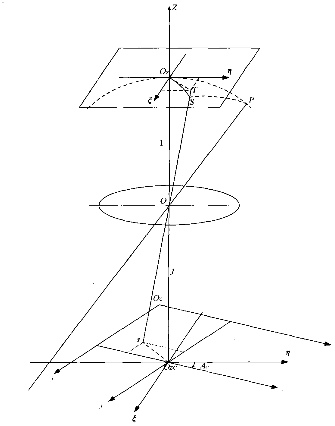
[0074] For photos I and III taken in different orientations, calculate the stellar-earth coordinates according to the exposure time, stellar catalog parameters and the calculation model of stellar-earth coordinates in Appendix F and H of GJB6304-2008 "2000 China Geodetic System" The CCD plane coordinates (x i ,y i ) s ;
[0075] The initial rough coordinates of the measuring station are Then the ideal coordinates (η i , ξ i ) s :
[0076]
[0077] For the photos I and III taken in different orientations, the imaging model is established by using the least square method as follows:
[0078] η I = f 1 ...
Embodiment 2
[0092] Embodiment 2: the digital zenith instrument rotation axis solving method as described in embodiment 1, wherein the different azimuth observation photographs described in the A step are the observation photographs of azimuth difference 180 ± 10 °; Used in the A step (6 ) formula can also use an affine transformation model or a projection transformation model. In the case of a large field of view, a quadratic model with 12 parameters or a cubic model with 20 parameters can be used to solve the quadratic or cubic rotation axis equation, using Newton iteration Law.
Embodiment 3
[0093] Embodiment 3: another kind of digital zenith instrument rotation axis solution method, comprises the following steps:
[0094] a. Establish the imaging model of observation photos from different azimuths
[0095] For photos I and III taken in different orientations, calculate the stellar-earth coordinates according to the exposure time, stellar catalog parameters and the calculation model of stellar-earth coordinates in Appendix F and H of GJB6304-2008 "2000 China Geodetic System" The CCD plane coordinates (x i ,y i ) s ;
[0096] The initial rough coordinates of the measuring station are Then the ideal coordinates (η i , ξ i ) s :
[0097]
[0098] For the photos I and III taken in different orientations, the imaging model is established by using the least square method as follows:
[0099] x I = F 1 ...
PUM
 Abstract
Description
Claims
Application Information
 - R&D
- Intellectual Property
- Life Sciences
- Materials
- Tech Scout
- Unparalleled Data Quality
- Higher Quality Content
- 60% Fewer Hallucinations
Browse by: Latest US Patents, China's latest patents, Technical Efficacy Thesaurus, Application Domain, Technology Topic, Popular Technical Reports.
© 2025 PatSnap. All rights reserved.Legal|Privacy policy|Modern Slavery Act Transparency Statement|Sitemap|About US| Contact US: help@patsnap.com


