
Optical emitter assembly and manufacture method thereof

A technology of optical emitters and components, which is applied in the coupling of electromagnetic emitters, electrical components, and optical waveguides, and can solve the problems of unbalanced solder joint stress of collimating lenses, damage to the stability of collimating lenses, and complicated welding methods

Inactive Publication Date: 2012-06-27
SHENZHEN GIGALIGHT TECH
View PDF3 Cites 9 Cited by
  • Summary
  • Abstract
  • Description
  • Claims
  • Application Information

AI Technical Summary

Problems solved by technology

But at present, the welding method of the collimating lens and the focusing lens is complicated, and it is easy to cause the stress imbalance of the solder joint of the collimating lens, and destroy the stability of the collimating lens

Method used

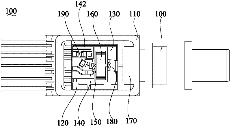
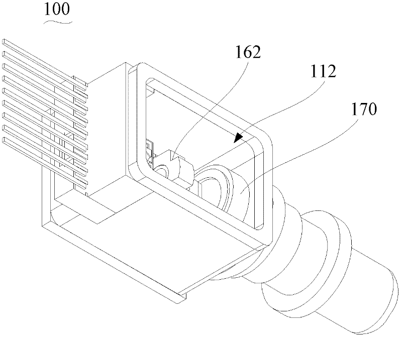
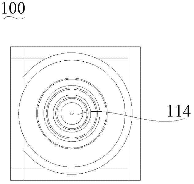

Image

  • Optical emitter assembly and manufacture method thereof
  • Optical emitter assembly and manufacture method thereof
  • Optical emitter assembly and manufacture method thereof

Examples


Embodiment Construction

[0030] In order to facilitate the understanding of the present invention, the present invention will be described more fully below with reference to the associated drawings. Preferred embodiments of the invention are shown in the accompanying drawings. However, the present invention can be embodied in many different forms and is not limited to the embodiments described herein. On the contrary, the purpose of providing these embodiments is to make the disclosure of the present invention more thorough and comprehensive.

[0031] It should be noted that when an element is referred to as being “fixed” to another element, it can be directly on the other element or there can also be an intervening element. When an element is referred to as being "connected to" another element, it can be directly connected to the other element or intervening elements may also be present. The terms "vertical," "horizontal," "left," "right," and similar expressions are used herein for purposes of ill...


PUM


Abstract

An optical emitter assembly comprises a casing, a circuit board, an optical emitter, a front lens and a rear lens. The casing is provided with a containing cavity, and a lateral wall of the casing is provided with an opening. The circuit board is contained in the containing cavity and connected with the bottom of the casing. The front lens is welded at the bottom of the casing through double light beams. An emitter is electrically connected onto the circuit board, and the optical emitter is located at a focus position of the front lens. The rear lens is arranged on one side of the front lens away from the optical emitter, the optical emitter, the front lens and the rear lens are arranged on the same optical axis, and openings are arranged on the optical axis. Due to the fact that the front lens is welded by the double light beams simultaneously, welding time is consistent, welding points after welding are good in symmetry, stress release of the welding points are the same, welding stability of the front lens can be ensured, and accordingly stability of an optical path can be ensured. Double light beam welding is fast, so that the problems of long time welding equipment occupation and equipment resource and labor resource consumption are avoided. The invention further provides a manufacture method of the optical emitter assembly.

Description

【Technical field】 [0001] The invention relates to the technical field of optical fiber communication, in particular to an optical transmitter and a manufacturing method thereof. 【Background technique】 [0002] Optical Transmitter Assembly (Transmitter Optical Subassembly abbreviated as TOSA) is the core device of modern optical fiber communication, 2.5Gb / s, 10Gb / s and above high-speed optical transmitters and optical transmitters used in Dense Wavelength Multiplexing (DWDM) systems Components, devices that require temperature control, are usually packaged in a butterfly package to ensure their functionality. The traditional front lens welding method is to use flat heat sink, single light speed laser welding method, the welding efficiency is low, and the welding quality is poor. The optical output of the optical transmitter component is to use a lens or an optical element similar to a lens to couple the output of the optical transmitter chip to a single-mode fiber or a singl...

Claims


Application Information

Patent Timeline
IPC IPC(8): G02B6/42H04B10/04H04B10/50
Inventor 黄立刚
Owner SHENZHEN GIGALIGHT TECH
Learn More