PH meter and calibration method thereof
A No. 1, liquid pool technology, applied in measuring devices, material analysis by electromagnetic means, instruments, etc., can solve the problems of wasting distilled water, buffer absorbent paper, creating storage conditions, and wasting buffer use, etc., to simplify the instrument and cumbersome procedures, ensure accuracy and precision, and ensure smooth results
- Summary
- Abstract
- Description
- Claims
- Application Information
AI Technical Summary
Problems solved by technology
Method used
Image
Examples
Embodiment 1
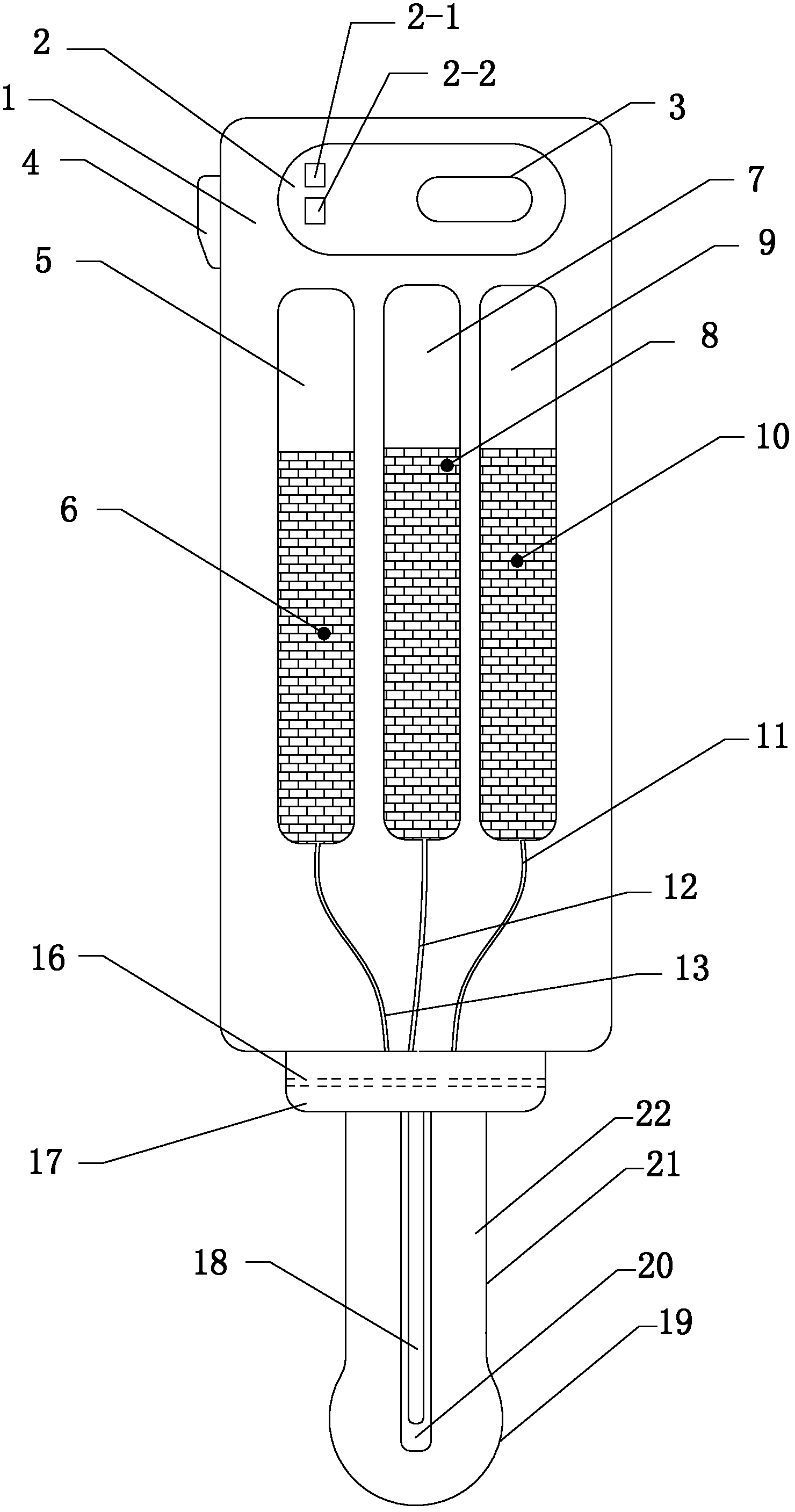
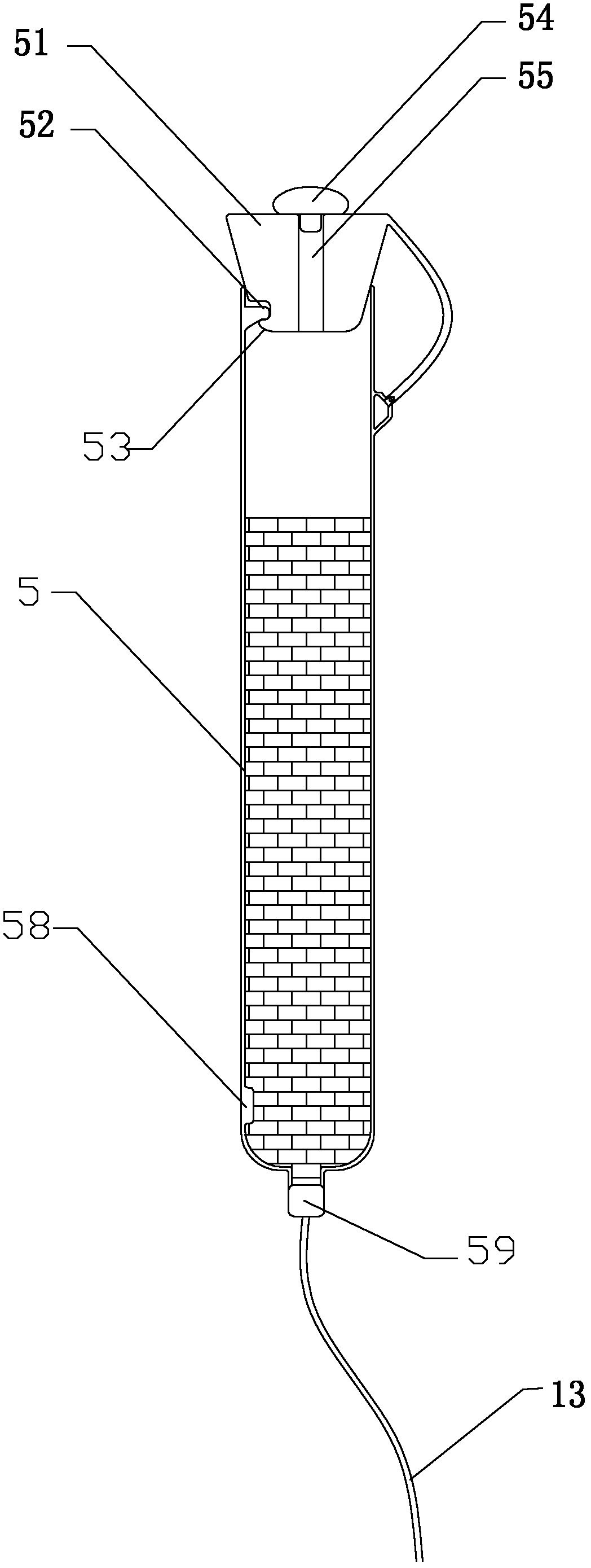
[0044] like figure 2 and image 3 As shown, a pH meter includes a housing 1 , a control circuit 3 , a calibration switch 4 , an indicating device, a glass electrode 22 , a reference electrode 18 and a reference solution 20 .
[0045] The control circuit 3 is located inside the top of the casing 1 . The calibration switch 4 is located outside the top of the housing 1 . The indicating device comprises a digital display window 2, an indicator light 2-1, and an alarm 2-2. The calibration switch 4 , the indicating device, the glass electrode 22 , and the reference electrode 18 are all electrically connected to the control circuit 3 . The glass electrode 22 is the same as the prior art, and generally consists of a glass strut 21 and a bulb 19 at the lower end of the glass strut 21 .
[0046] There are three liquid pools inside the housing 1 , namely No. 1 liquid pool 5 , No. 2 liquid pool 7 , and No. 3 liquid pool 9 . No. 1 buffer solution 6 is housed in No. 1 liquid pool 5, N...
Embodiment 2
[0057] The difference between this embodiment and the first embodiment is that the No. 3 liquid pool 9 is not installed in the inner shell 1 of the pH meter.
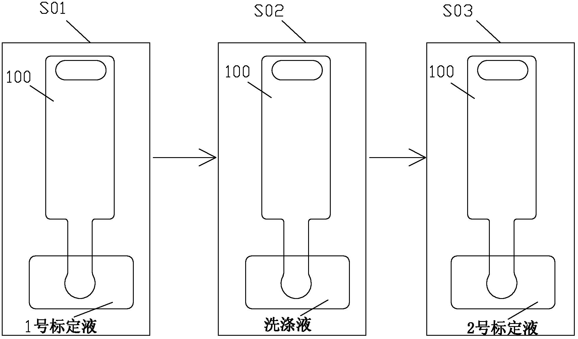
[0058] like Figure 4 As shown, the calibration method of this embodiment is as follows:
[0059] A) Inject No. 1 buffer 6 into No. 1 liquid pool 5, and inject No. 2 buffer 8 into No. 2 liquid pool 7; the operator can set No. 1 buffer 6 and No. 2 buffer 8 through the control circuit 3 Of course, you can also check the remaining days of the shelf life through the digital display window 2;
[0060]B) Hang the pH meter on the test bench, and place a beaker under it, which is used to receive the liquid flowing from the pH meter, and the liquid in the beaker does not contact the glass electrode 22 of the pH meter. Press the calibration switch 4, the control circuit 3 detects whether the buffer solution in the liquid pool is normal: the control circuit 3 receives the signals of the first sensing probe 58 and the second sens...
Embodiment 3
[0065] like Figure 7 and Figure 8 As shown, the difference between the present embodiment and the second embodiment is that a movable beaker 25 is movably connected to the bottom of the housing 1 . The movable beaker 25 is used to hold the liquid that the pH meter sheds during the calibration process, replacing the beaker in the second embodiment.
[0066] Compared with the second embodiment, the calibration method of this embodiment adds the following step C1 between step C and step D: Figure 8 As shown, the control circuit 3 commands the action of the movable beaker 25, and pours the liquid in the movable beaker 25. After pouring, as Figure 7 As shown, the movable beaker 25 resets so that the bulb body 19 of the glass electrode 22 is located in the movable beaker 25 . Step C1 can also be repeated between step C and step E.
[0067] In addition, since the movable beaker 25 can make the bulb body 19 of the glass electrode 22 soak in the liquid in the movable beaker 25,...
PUM
 Abstract
Description
Claims
Application Information
 - R&D Engineer
- R&D Manager
- IP Professional
- Industry Leading Data Capabilities
- Powerful AI technology
- Patent DNA Extraction
Browse by: Latest US Patents, China's latest patents, Technical Efficacy Thesaurus, Application Domain, Technology Topic, Popular Technical Reports.
© 2024 PatSnap. All rights reserved.Legal|Privacy policy|Modern Slavery Act Transparency Statement|Sitemap|About US| Contact US: help@patsnap.com


