Secondary speed reduction box applied on agricultural irrigation driving equipment

A driving equipment, secondary deceleration technology, applied in the field of machinery, can solve the problems of low transmission efficiency, large footprint of the worm gear box, large volume of the worm gear box, etc., to achieve smooth operation, less damage, and large bearing capacity Effect

Inactive Publication Date: 2012-06-27
浙江康明斯机械有限公司
View PDF6 Cites 3 Cited by
  • Summary
  • Abstract
  • Description
  • Claims
  • Application Information

AI Technical Summary

Problems solved by technology

[0002] The two-stage reduction box in the driving device of agricultural irrigation driving equipment currently used in the market generally includes a worm gear box, and a worm gear and a worm are installed in the worm gear box, and the worm gear and the worm are meshed and connected, and one end of the worm is connected to the output shaft of the motor. connection, the worm wheel is sleeved with a rotating shaft, and the output end of the rotating shaft is fixedly connected with a connection plate and connected to the hub through the connection plate. There is an oil storage chamber between the worm wheel and the worm. The existing problem is: The Archimedes worm gear pair is used for transmission, and its transmission efficiency is low, only 40%. At the same time, this kind of transmission makes the volume of the worm gear box large, causing the entire worm gear box to occupy a large area.

Method used


Image

  • Secondary speed reduction box applied on agricultural irrigation driving equipment
  • Secondary speed reduction box applied on agricultural irrigation driving equipment
  • Secondary speed reduction box applied on agricultural irrigation driving equipment

Examples


Embodiment Construction

[0026] The following are specific embodiments of the present invention and in conjunction with the accompanying drawings, the technical solutions of the present invention are further described, but the present invention is not limited to these embodiments.

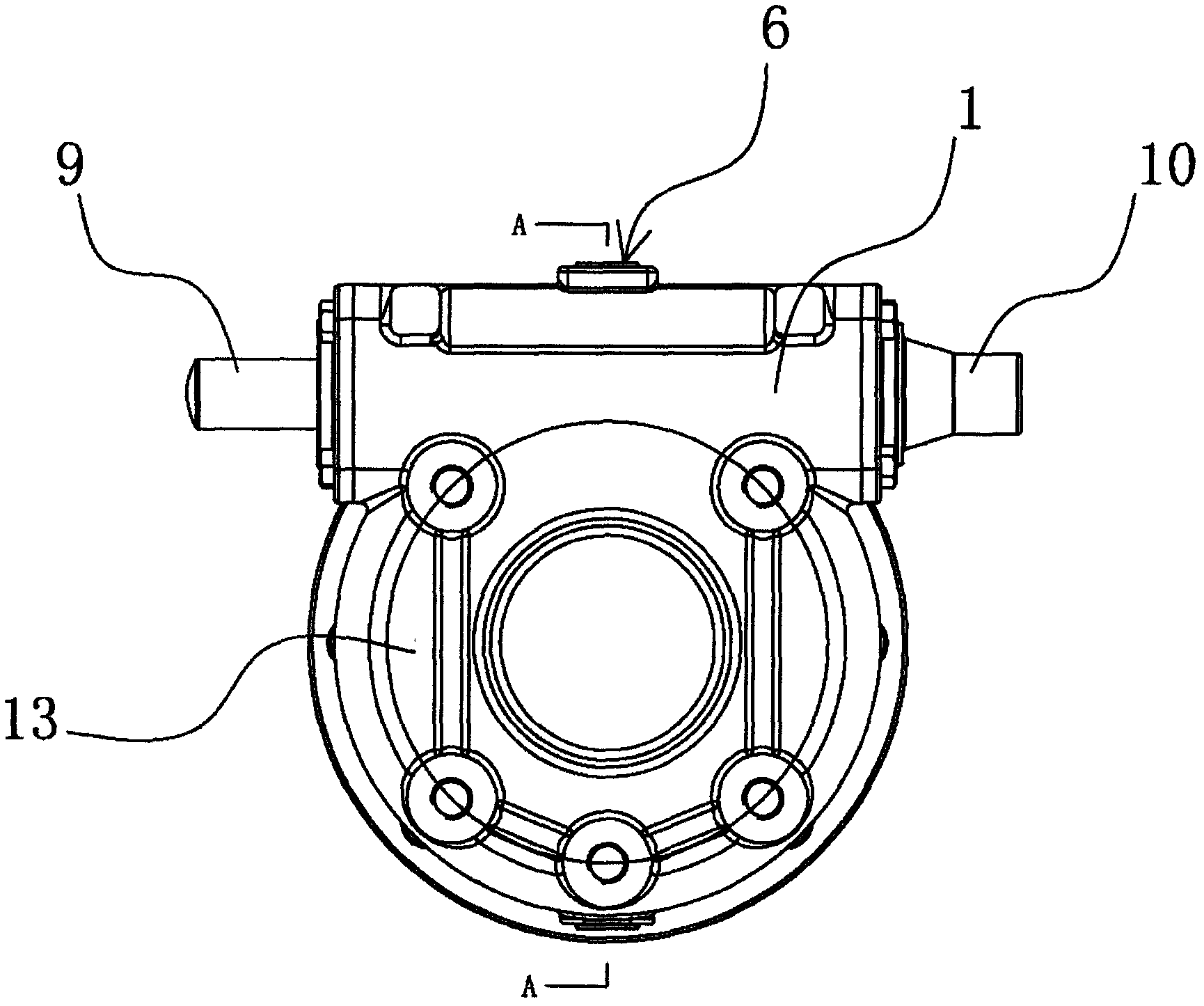
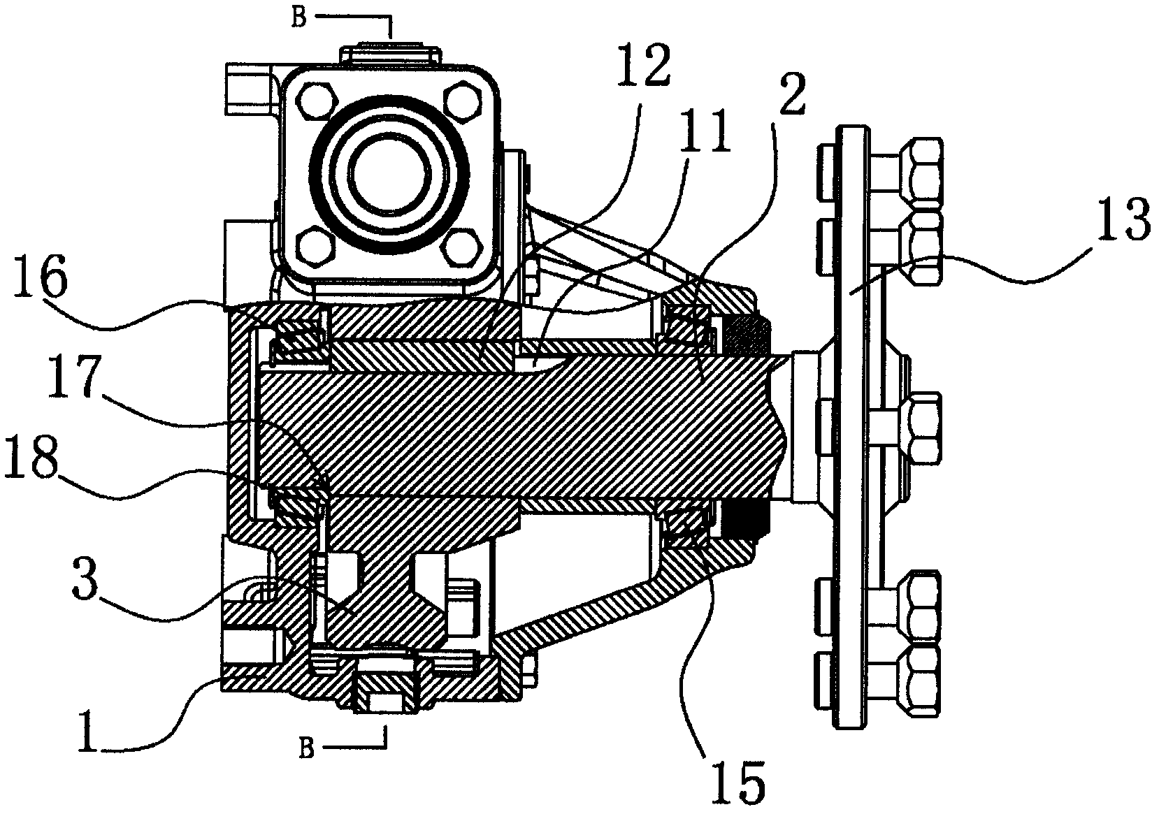
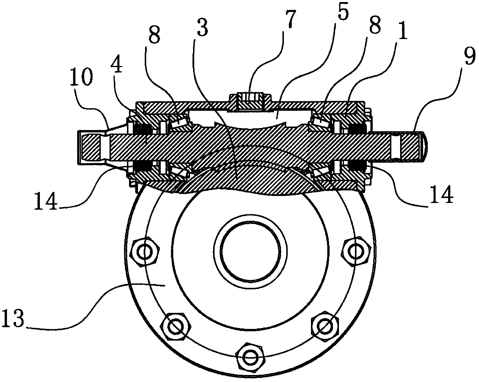
[0027] Such as figure 1 , 2 As shown in and 3, the two-stage reduction box used for agricultural irrigation driving equipment includes a worm gear box 1 and a rotating shaft 2, and a worm wheel 3 and a worm 4 are installed in the worm gear box 1, and there is a lubricating gear box in the worm gear box 1. The oil storage chamber 5 of the oil, the upper end wall of the worm gear casing 1 has an oil inlet hole 6 with an internal thread, and the oil inlet hole 6 is threaded with an oil plug 7, and the oil inlet hole 6 communicates with the oil storage chamber 5. The two ends of the worm 4 are provided with tapered roller bearings 8 respectively, and both ends of the worm 4 pass through the worm gear box 1, the front end of t...


PUM


Abstract

The invention provides a secondary speed reduction box applied on agricultural irrigation driving equipment, which belongs to the technical field of machinery and solves the problems of low transmission efficiency and large size of an existing secondary speed reduction box. The secondary speed reduction box applied on the agricultural irrigation driving equipment comprises a worm gear box and a rotary shaft, a worm gear and a worm are mounted in the worm gear box, an oil storage cavity used for storing lubricating oil is arranged in the worm gear box, two bearings are sleeved at two ends of the worm respectively and two ends of the worm penetrate through the worm gear box, the two bearings are fixedly mounted on the inner wall of the worm gear box, the worm gear is sleeved on the rotary shaft through a circumferential limit structure, an output end of the rotary shaft is fixedly connected with a connecting disc used for being connected with a hub, and the worm gear and the worm are connected through a planar secondary enveloping ring-surface worm pair. The secondary speed reduction box has the advantages of high transmission efficiency, stable transmission, long service life and small size.

Description

technical field [0001] The invention belongs to the technical field of machinery and relates to a two-stage reduction box, in particular to a two-stage reduction box applied to agricultural irrigation drive equipment. Background technique [0002] The two-stage reduction box in the driving device of agricultural irrigation driving equipment currently used in the market generally includes a worm gear box, and a worm wheel and a worm are installed in the worm gear box, and the worm wheel and the worm are engaged and connected. One end of the worm is connected to the output shaft of the motor. connection, the worm wheel is sleeved with a rotating shaft, and the output end of the rotating shaft is fixedly connected with a connection plate and connected to the hub through the connection plate. There is an oil storage chamber between the worm wheel and the worm. The existing problem is: The Archimedes worm gear pair is used for transmission, and its transmission efficiency is low,...

Claims


Application Information

Patent Timeline
IPC IPC(8): F16H1/16F16H57/039F16H57/029F16H57/021F16H57/04
Inventor 林振
Owner 浙江康明斯机械有限公司
Why Eureka
Try Eureka