
Method for controlling movement of knee joints of artificial limbs

A control method and knee joint technology, applied in the field of prosthetic knee joints, can solve problems such as acquisition methods, complicated problems, and lack of multi-axis prosthetic knee angle information, so as to avoid easy wear, simplify detection difficulty, and eliminate multi-valued problems Effect

Active Publication Date: 2012-06-27
HEBEI UNIV OF TECH
View PDF5 Cites 28 Cited by
  • Summary
  • Abstract
  • Description
  • Claims
  • Application Information

AI Technical Summary

Problems solved by technology

These existing technologies are all based on the control of the angle sensor, there is no special control method related to the specific multi-axis prosthetic knee joint motion, and there is no method for obtaining angle information of the multi-axis prosthetic knee joint, and the angle sensor is applied to multiple Axle joints have a double-value problem corresponding to the angle of rotation axis and the bending angle of the prosthetic knee joint, which makes the problem more complicated

Method used

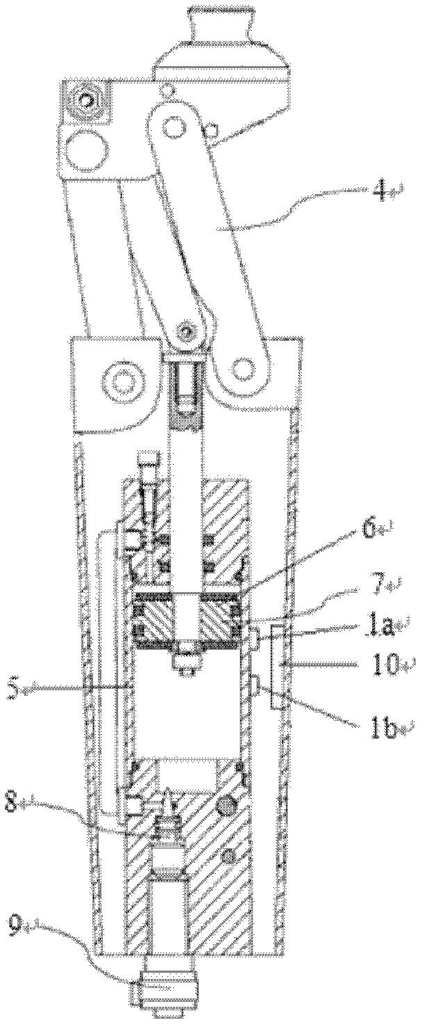

Image

  • Method for controlling movement of knee joints of artificial limbs
  • Method for controlling movement of knee joints of artificial limbs
  • Method for controlling movement of knee joints of artificial limbs

Examples


Embodiment 1

[0036] The situation of the wearer of the prosthesis belt of the four-link above-the-knee prosthesis knee joint is: male, 23 years old, with a height of 170cm and a weight of 62kg, who has worn the prosthetic knee joint for 3 years.

[0037] The method for controlling the motion of the prosthetic knee joint of the prosthetic wearer, the steps are as follows:

[0038] The first step is to install the control parts of the prosthetic knee joint

[0039] The structure of the knee joint body of the four-link upper knee prosthesis used is as above figure 2 The illustrated embodiment includes a four-bar linkage mechanism 4 , a cylinder block 5 , a cylinder piston 6 , a magnet 7 embedded in the cylinder piston, an air cavity needle valve 8 , a stepping motor 9 and a microcontroller 10 .

[0040] The four-link over-the-knee prosthetic knee joint body is installed on the limb of the prosthetic wearer according to known methods, and the walking speed and current step of the prosthetic ...


PUM


Abstract

The invention relates to a method for controlling movement of knee joints of artificial limbs, which relates to knee joints of artificial limbs. Steps of the method include that a control component for a knee joint of an artificial limb is mounted and comprises a four-bar linkage on-knee artificial limb knee joint body and a sensor, a Hall sensor is mounted at a boundary position at which a piston of a cylinder moves from a supporting phase to a swinging phase, the piston of the cylinder can move to an artificial limb knee joint locking position, and another Hall sensor is mounted at the artificial limb knee joint locking position; a microcontroller detects the tread period of an artificial limb wearer so as to judge stepping speed, the Hall sensors judge a tread time phase, the microcontroller controls opening of a needle valve of an air cavity, and damping generated in a cylinder body of the cylinder is adjusted so as to adjust the stepping speed; finally, the artificial limb wearer walks normally, when at the swinging phase, the needle valve of the air cavity moves according to an opening value corresponding to the stepping speed, after being in the supporting phase, the needle valve of the air cavity is closed completely, the value of the damping maximizes, and then the knee joint of the artificial limb is locked; and shortcomings that the prior art is lack of a method for controlling movement of a knee joint of a multi-axis artificial limb.

Description

technical field [0001] The technical solution of the invention relates to a prosthetic knee joint, in particular to a control method for the motion of the prosthetic knee joint. Background technique [0002] For lower limb amputees, the installation of prosthetic limbs with compensatory movement function is an important means of restoring mobility. Most of the control methods of the existing prosthetic knee joint products on the market are to adjust the motion of the prosthetic knee joint by adjusting the resistance of the prosthetic knee joint, that is, the force that hinders joint movement in the direction of flexion and extension of the prosthetic knee joint. There are two ways to adjust the resistance of the prosthetic knee joint: manual adjustment and automatic adjustment. The manual adjustment method is to manually change the resistance of the prosthetic knee joint on the knee. After the resistance adjustment, the resistance remains approximately constant in a certain...

Claims


Application Information

Patent Timeline
Patent Type & Authority Applications(China)
IPC IPC(8): A61F2/70
Inventor 杨鹏陈玲玲岳华王蒙耿艳利
Owner HEBEI UNIV OF TECH
Learn More