MOSFET-based auto-excitation type Zeta converter

A converter and self-excited technology, which is applied in the direction of output power conversion device, DC power input conversion to DC power output, instruments, etc., can solve the problem of insufficient efficiency of self-excited Zeta converters, and achieve high efficiency and circuit The effect of simple structure

Active Publication Date: 2012-06-20
金湖县农副产品营销协会
View PDF3 Cites 3 Cited by
  • Summary
  • Abstract
  • Description
  • Claims
  • Application Information

AI Technical Summary

Problems solved by technology

[0003] In order to overcome the insufficient efficiency of the BJT-based self-excited Zeta converter and the deficiency that it is only suitable for small power, the present invention provides a MOSFET (Metal Oxide Semiconductor Field Effect Transistor) based MOSFET (Metal Oxide Semiconductor Field Effect Transistor) with high efficiency and wide applicable power range. Self-excited Zeta Converter

Method used


Image

  • MOSFET-based auto-excitation type Zeta converter
  • MOSFET-based auto-excitation type Zeta converter
  • MOSFET-based auto-excitation type Zeta converter

Examples


Embodiment 1

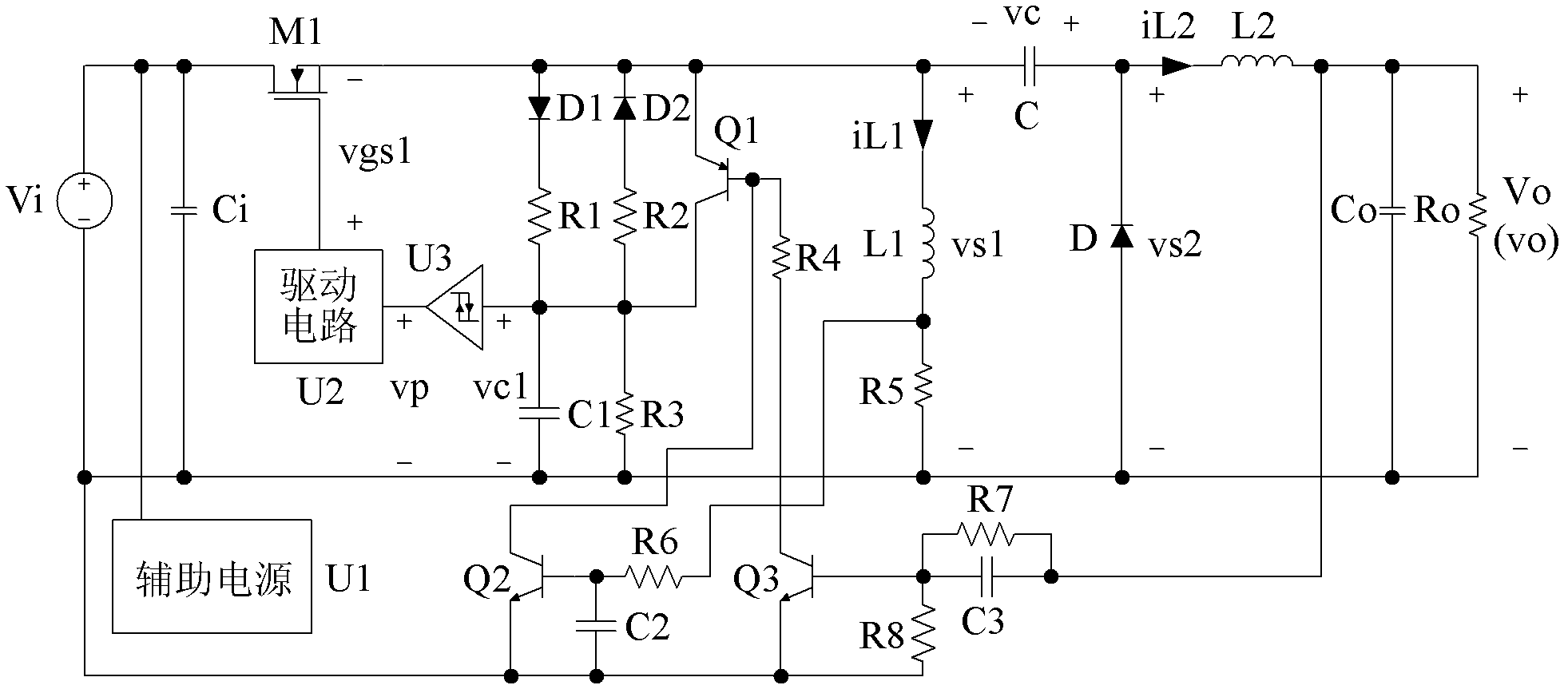
[0022] refer to figure 2 , Figure 4 and Figure 5, a MOSFET-based self-excited Zeta converter, including the Zeta converter main circuit composed of input capacitor Ci, N-type MOSFET M1, inductor L1, capacitor C, diode D, inductor L2 and capacitor Co, the input capacitor Ci and The DC voltage source Vi is connected in parallel, the voltage across the output capacitor Co is the DC output voltage Vo, the load Ro is connected in parallel with the output capacitor Co, the positive terminal of the DC voltage source Vi is connected to the drain of the N-type MOSFET M1, and the source of the N-type MOSFET M1 It is connected to one end of the inductor L1 and one end of the capacitor C, the other end of the inductor L1 is connected to one end of the resistor R5, the other end of the resistor R5 is connected to the negative end of the DC voltage source Vi, and the other end of the capacitor C is connected to the cathode of the diode D and One end of the inductor L2 is connected, the...

Embodiment 2

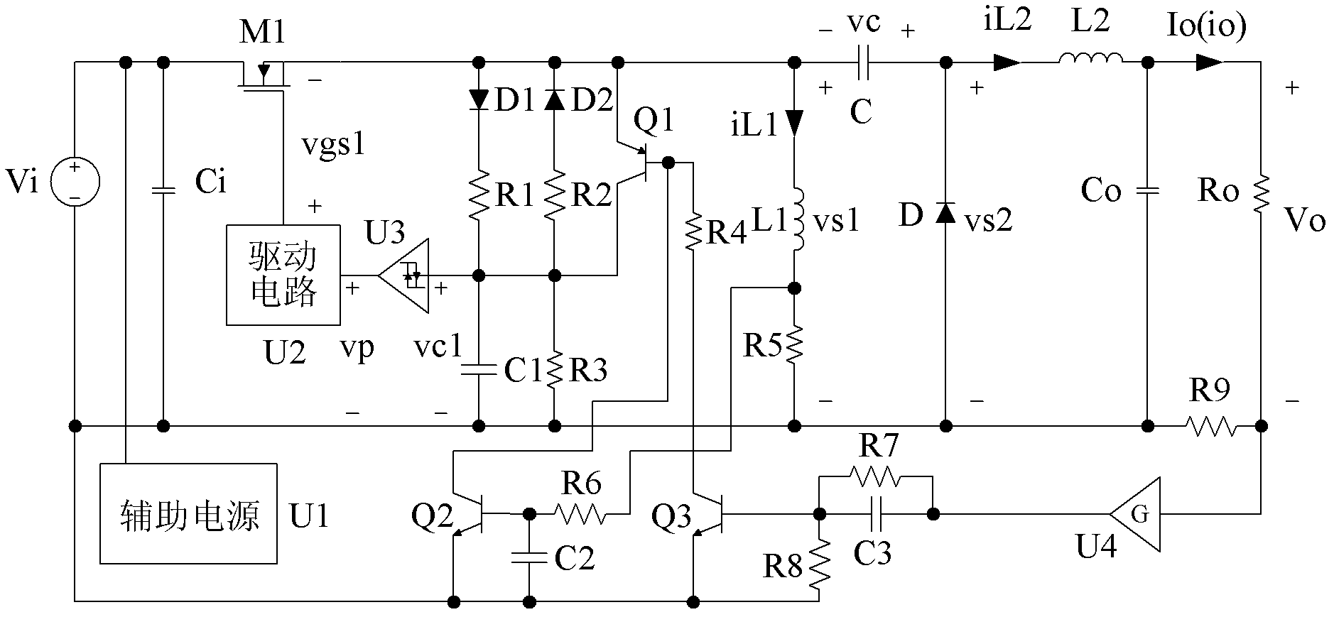
[0030] refer to image 3 , Figure 4 and Figure 6 , the present embodiment also includes a current feedback branch, the current feedback branch includes a detection resistor R9, a voltage amplifier U4, a resistor R7, a capacitor C3, a resistor R8, an NPN type BJT Q3, a resistor R4, and a PNP type BJT Q1, and the detection resistor R9 and the load Ro form a series branch, the series branch is connected in parallel with the output capacitor Co, one end of the detection resistor R9 is connected to the negative end of the DC voltage source Vi, the other end of the detection resistor R9 is connected to one end of the load Ro and the voltage amplifier U4 connected to the input of the resistor R7 and the capacitor C3 to form a parallel branch, one end of the parallel branch is connected to the output of the voltage amplifier U4, the other end of the parallel branch is connected to one end of the resistor R8 and the NPN type BJT Q3 The base is connected, the emitter of the NPN BJT ...


PUM


Abstract

An MOSFET (Metal-Oxide -Semiconductor Field Effect Transistor)-based auto-excitation type Zeta converter comprises a Zeta converter main loop consisting of an input capacitor Ci, an N-type MOSFET M1, an inductor L1, a capacitor C, a diode D, an inductor L2 and a capacitor Co. The converter further comprises an auxiliary power supply U1, and adopts a single-MOSFET basic auto-excitation unit circuit consisting of the N-type MOSFET M1, a diode D1, a diode D2, a resistor R1, a resistor R2, a resistor R3, a capacitor C1, a hysteresis comparator U3 and a drive circuit U2. The MOSFET-based auto-excitation type Zeta converter provided by the invention has the advantages of higher efficiency and wider applicable power range.

Description

technical field [0001] The invention relates to a self-excited direct current-direct current (DC-DC) converter, which is applied to a switching voltage-stabilizing or current-stabilizing power supply, a high-brightness LED drive circuit, etc., in particular to a self-excited Zeta converter. Background technique [0002] Compared with linear (stabilized voltage or steady current) regulators and other excited DC-DC converters, self-excited DC-DC converters have significant advantages of high cost performance. figure 1 Given is a self-excited Zeta converter based on BJT (bipolar transistor), including input capacitor Ci, PNP type BJT Q1, diode D1, inductor L1, capacitor C, diode D, inductor L2 and output capacitor The main circuit of the Zeta converter composed of Co, the input capacitor Ci is connected in parallel with the DC voltage source Vi, the voltage across the output capacitor Co is the DC output voltage Vo, the load Ro is connected in parallel with the output capacitor...

Claims


Application Information

Patent Timeline
IPC IPC(8): H02M3/158H05B37/02
Inventor 陈怡南余荣
Owner 金湖县农副产品营销协会
Why Eureka
Try Eureka