Power transmitting apparatus, power receiving apparatus, and power transmission system
A power receiving device and power transmission technology, applied in circuit devices, electromagnetic wave systems, battery circuit devices, etc., can solve the problems of large capacity of passive electrodes, electromagnetic field leakage, potential changes, etc.
- Summary
- Abstract
- Description
- Claims
- Application Information
AI Technical Summary
Problems solved by technology
Method used
Image
Examples
no. 1 approach
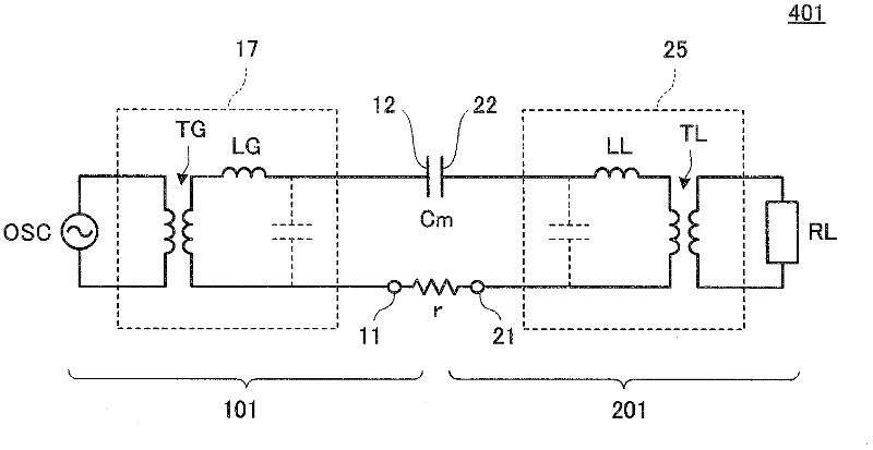
[0132] figure 2 It is a schematic circuit diagram of the electric power transmission system 401 which concerns on 1st Embodiment. This power transmission system 401 is composed of a power transmission device 101 and a power reception device 201 . Power transmitting device 101 includes power transmitting device side passive electrode 11 and power transmitting device side active electrode 12 , while power receiving device 201 includes power receiving device side passive electrode 21 and power receiving device side active electrode 22 .
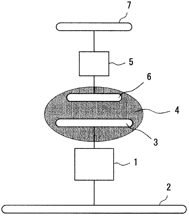
[0133] A high-frequency high-voltage generating circuit 13 is connected between the power transmission device side active electrode 12 and the power transmission device side passive electrode 11 . A step-down circuit 25 is connected between the power receiving device-side active electrode 22 and the power receiving device-side passive electrode 21 , and a load circuit RL is connected to the step-down circuit 25 .
[0134] The high-frequency h...
no. 2 approach
[0146] Figure 5 (A) is a perspective view viewed obliquely from the rear of power receiving device 202A according to the second embodiment, Figure 5 (B) is a cross-sectional view of the power receiving device 202A. The case 20 of this power receiving device 202A is a molded body of an insulator (dielectric) material. Inside the case, a power receiving device side passive electrode 21N is formed along the case 20 . On the back surface of the case 20, a power receiving device side passive electrode connection conductor 21C is exposed and formed to conduct with the power receiving device side passive electrode 21N. In addition, a power receiving device side active electrode 22 is formed along the case 20 in the vicinity of the bottom surface of the case 20 .
[0147] Figure 6 It is a perspective view of the usage form of the electric power transmission system 402 which concerns on 2nd Embodiment. In this example, the power transmitting device 102 has a size capable of acc...
no. 3 approach
[0154] Figure 9 (A) is a perspective view of a usage mode of the power transmission system 403 according to the third embodiment, Figure 9 (B) is a side view showing the state immediately before the power receiving device 203 is placed with respect to the power transmitting device 103 . The upper surface of the power transmission device 103 is a placement surface. Place the power receiving device 203 on the placement surface.
[0155] On the casing of the power transmission device 103 , the power transmission device side passive electrode 11 is provided on the placement surface, and the power transmission device side active electrode 12 is provided along the placement surface. The power receiving device side passive electrode 21 is provided on the bottom surface of the power receiving device 203 , and the power receiving device side active electrode 22 is provided along the bottom surface of the power receiving device 203 .
[0156] In the state where the power receiving ...
PUM
 Abstract
Description
Claims
Application Information
 - Generate Ideas
- Intellectual Property
- Life Sciences
- Materials
- Tech Scout
- Unparalleled Data Quality
- Higher Quality Content
- 60% Fewer Hallucinations
Browse by: Latest US Patents, China's latest patents, Technical Efficacy Thesaurus, Application Domain, Technology Topic, Popular Technical Reports.
© 2025 PatSnap. All rights reserved.Legal|Privacy policy|Modern Slavery Act Transparency Statement|Sitemap|About US| Contact US: help@patsnap.com


