
Power transmitting apparatus, power receiving apparatus, and power transmission system

A power receiving device and power transmission technology, applied in circuit devices, electromagnetic wave systems, battery circuit devices, etc., can solve problems such as potential changes, excessive parasitic capacitance, and excessive parasitic electricity

Inactive Publication Date: 2014-02-26
MURATA MFG CO LTD
View PDF6 Cites 0 Cited by
  • Summary
  • Abstract
  • Description
  • Claims
  • Application Information

AI Technical Summary

Problems solved by technology

When the passive electrode of the power transmitting device, the active electrode of the power transmitting device, the active electrode of the power receiving device, and the passive electrode of the power receiving device are arranged longitudinally in a space that has become narrower in the longitudinal direction, the parasitic capacitance prone to oversize
In the power transmission system of Patent Document 2, since the active electrode and the passive electrode are arranged adjacent to one surface, the parasitic capacitance generated between the active electrode and the passive electrode and the circuit board arranged close to these electrodes also prone to oversize
Therefore, in any method, there are problems of increased coupling degree and low transmission efficiency.
[0009] In addition, Patent Document 1 and Patent Document 2 cannot make the capacity of the passive electrode pair of the power transmitting device and the power receiving device too large in terms of structure. The smaller the capacitance of the passive electrode pair is, the more potential the two passive electrodes generate. Variety
The problem is that the potential change of the passive electrode of the power transmitting device and the power receiving device becomes a cause of leakage of unnecessary electromagnetic fields, or it becomes a cause of a change in the ground potential of the power transmitting device and the power receiving device

Method used


Image

  • Power transmitting apparatus, power receiving apparatus, and power transmission system
  • Power transmitting apparatus, power receiving apparatus, and power transmission system
  • Power transmitting apparatus, power receiving apparatus, and power transmission system

Examples


no. 1 approach

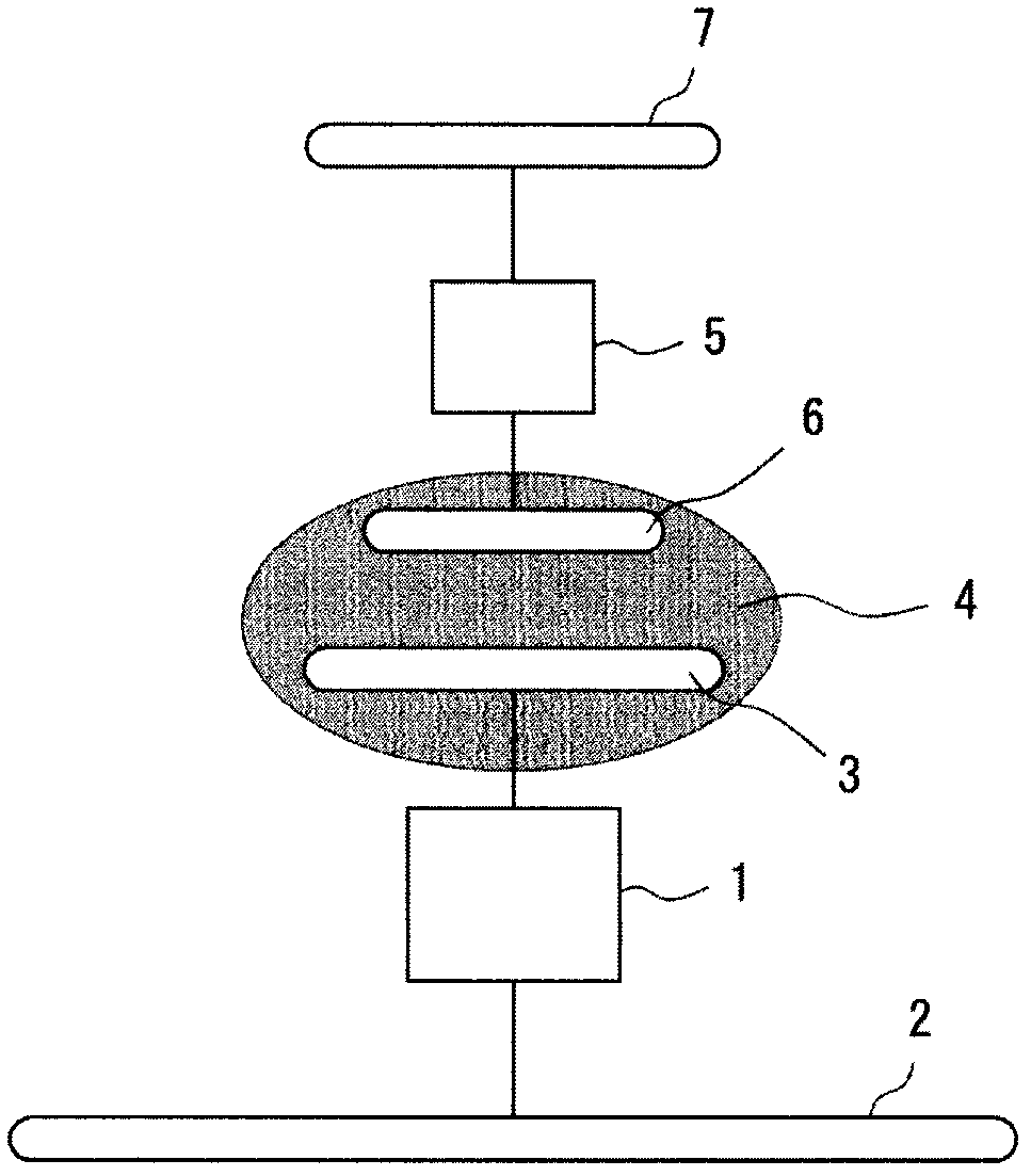
[0137] figure 2 It is a schematic circuit diagram of the electric power transmission system 401 which concerns on 1st Embodiment. This power transmission system 401 is composed of a power transmission device 101 and a power reception device 201 . Power transmitting device 101 includes power transmitting device side passive electrode 11 and power transmitting device side active electrode 12 , while power receiving device 201 includes power receiving device side passive electrode 21 and power receiving device side active electrode 22 .

[0138] A high-frequency high-voltage generating circuit 13 is connected between the power transmission device side active electrode 12 and the power transmission device side passive electrode 11 . A step-down circuit 25 is connected between the power receiving device-side active electrode 22 and the power receiving device-side passive electrode 21 , and a load circuit RL is connected to the step-down circuit 25 .

[0139] The high-frequency h...

no. 2 approach

[0151] Figure 5 (A) is a perspective view viewed obliquely from the rear of the power receiving device 202A according to the second embodiment, Figure 5 (B) is a cross-sectional view of the power receiving device 202A. The case 20 of the power receiving device 202A is a molded body of an insulator (dielectric) material. Inside the case, a power receiving device side passive electrode 21N is formed along the case 20 . A power receiving device side passive electrode connection conductor 21C that is electrically connected to the power receiving device side passive electrode 21N is exposed on the back surface of the case 20 . In addition, a power receiving device side active electrode 22 is formed along the case 20 in the vicinity of the bottom surface of the case 20 .

[0152] Figure 6 It is a perspective view of the usage form of the electric power transmission system 402 which concerns on 2nd Embodiment. In this example, the power transmitting device 102 has a size capa...

no. 3 approach

[0159] Figure 9 (A) is a perspective view of a usage mode of the power transmission system 403 according to the third embodiment, Figure 9 (B) is a side view showing the state immediately before the power receiving device 203 is placed with respect to the power transmitting device 103 . The upper surface of the power transmission device 103 is a placement surface. Place the power receiving device 203 on the placement surface.

[0160] On the casing of the power transmission device 103 , the power transmission device side passive electrode 11 is provided on the placement surface, and the power transmission device side active electrode 12 is provided along the placement surface. The power receiving device side passive electrode 21 is provided on the bottom surface of the power receiving device 203 , and the power receiving device side active electrode 22 is provided along the bottom surface of the power receiving device 203 .

[0161] In the state where the power receiving ...


PUM


Abstract

A power transmitting apparatus (101) has a power transmitting apparatus side active electrode (12) provided within the casing thereof along a seat (10D). A power transmitting apparatus side passive electrode (11) is exposed on a backrest (10B). A power receiving apparatus (201) has a power receiving apparatus side active electrode (22) formed along the bottom surface thereof. A power receiving apparatus side passive electrode (21) is formed on the outer surface of the casing (20) of the power receiving apparatus (201). By mounting the power receiving apparatus (201) on a mounting portion of the power transmitting apparatus (101), the power receiving apparatus side active electrode (22) faces the power transmitting apparatus side active electrode (12) with a dielectric layer therebetween, and the power receiving apparatus side passive electrode (21) is directly electrically connected to the power transmitting apparatus side passive electrode (11).

Description

technical field [0001] The invention relates to an electric power transmission device, a power receiving device and a power transmission system. Background technique [0002] As a typical system for transmitting power between two devices by bringing two devices close to each other, there is known a magnetic field coupling type power transmission system that uses a magnetic field to transmit power from the primary coil of the power transmitting device to the secondary coil of the power receiving device . However, in the case of transmitting power through magnetic field coupling, the magnitude of the magnetic flux passing through each coil has a great influence on the electromotive force, so the relative positional relationship between the primary coil and the secondary coil has high precision requirements. In addition, since a coil is used, it is difficult to reduce the size of the device. [0003] On the other hand, electric field coupling type wireless power transmission ...

Claims


Application Information

Patent Timeline
Patent Type & Authority Patents(China)
IPC IPC(8): H02J7/00H02J17/00
CPCH02J7/025H02J7/0044H02J50/80H02J50/40H02J50/70H02J50/10H02J7/02H02J5/00
Inventor 市川敬一乡间真治加藤数矢
Owner MURATA MFG CO LTD
Learn More